8
6. With the parking brake set and while continuing to apply the brakes, shift the transmission back into “Park” and allow the engine
speed to stabilize.
7. Once again, shift the transmission into gear while applying the brakes and having the parking brake set. Check the engine speed
to verify that the engine idles at approximately 700 rpm.
8. Do not reconnect the yellow wire to the fast idle solenoid at this time.
NOTE: The idle speed required for your vehicle may differ. Set the engine idle for a speed that best suits y
our application.
9. Shift the engine back into “Park” and shut off the engine.
SETTING THE THROTTLE POSITION SENSOR (TPS)
TPS Adjustment and Jumper Placement
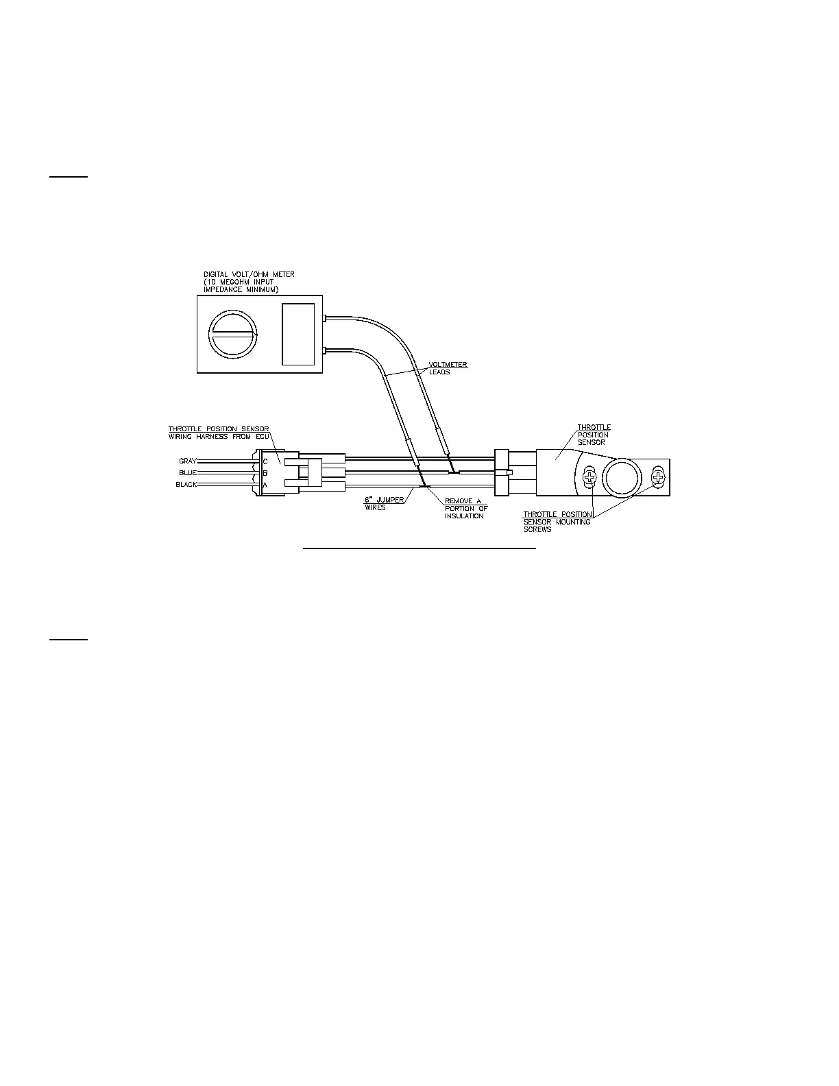
Figure 4
The setting of the throttle position sensor is critical in the operation of the Digital ECU and is best accomplished by using a digital
voltmeter. To adjust, follow the instructions carefully.
NOTE: Fuel delivery can NOT BE ADJUSTED by changing the positions of the TPS. The TPS must be set in the position outlined
below.
1. Unplug the three-position connector from the TPS and attach jumper wires between the TPS and the connector.
2. Remove a portion of the insulation on the jumper wires connecting to both the black and the blue wires leading to the TPS as
shown in Figure 4.
3. Attach the positive (+) lead of a digital volt meter to the jumper wire connected to the blue wire.
4. Attach the negative (-) lead of a digital volt meter to the jumper wire connected to the black wire.
5. Turn the ignition key to the “RUN” position. Do not start the engine.
6. Slightly loosen the two screws that hold the TPS in place with a Phillips screwdriver.
7. Adjust the TPS until the voltage between the blue and black wire measures 0.63 to 0.65 volts.
8. Tighten the two screws that hold the TPS in place and verify that the voltage between the blue and black wires on the TPS
continues to read between 0.63 to 0.65 volts. Readjust the TPS if necessary to obtain this voltage reading.
9. Turn the ignition key to the “OFF” position.
10. Remove the jumper wires and plug the three-position connector back into the TPS, ensuring that the safety latch snaps into place.