Do you have a question about the Homa HCON 25 and is the answer not in the manual?
Defines the intended use of the switchgear in domestic and municipal sewage stations.
Details the HCON 25's capabilities for automatic level control and pump triggering.
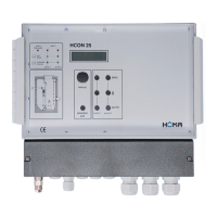
Lists the key features, functions, and operational modes of the HCON 25 control unit.
Outlines additional features and components that may be included based on the order.
Explains how to check and adjust settings using the digital potentiometer and display.
Describes the function of buttons like Menu, Selection Quit, MAN, and AUTO.
Details the meaning of different LED indicator lights for operational status and faults.
Explains what information is shown on the LC display during operation and fault conditions.
Presents a table detailing various adjustable settings and their explanations.
Provides further details on specific settings like pump monitoring, runtime limit, and fault memory.
Lists error messages, their possible causes, and recommended corrections.
Explains that some settings cannot be adjusted and suggests checking service mode.
Provides dimensions and mounting instructions for the control unit's enclosure.
Details the standard and optional hose connection types and installation requirements.
Covers essential electrical connections, power supply, and pump wiring for 3~ and 1~ motors.
Explains the function of warning and limiting contacts for pump thermal protection.
Describes the terminals used for outputting malfunction messages.
Explains the connection and function of the dry run protection port.
Shows diagrams for connecting float switches in different configurations.
Details the connection and settings for external 4-20 mA level sensors.
Explains the use and connection of analog outlets for control systems.
Illustrates the electrical connection diagram for three-phase motors.
Illustrates the electrical connection diagram for single-phase motors.
Shows the drilling pattern and dimensions for mounting the control unit enclosure.
| Brand | Homa |
|---|---|
| Model | HCON 25 |
| Category | Plumbing Product |
| Language | English |