7 - English
INSTALLING THE TINES
See Figure 5.
The cultivator has four tines — two inner tines stamped B
and C, and two outer tines stamped A and D. For correct
operation of the unit, the tines must be installed in the cor-
rect orientation.
Lean the unit back on its wheels so that the handlebar
rests on the ground.
Place tine C on the tine shaft to the left of the gear box.
The stamped side of the tine should face away from the
gear box.
Place tine B on the tine shaft to the right of the gear box.
The stamped side of the tine should face away from the
gear box.
Place a felt washer on each side of the tine shaft, and
slide to rest against the inner tines.
Place the outer tine labeled D on the left side of the tine
shaft. The stamped side should face in toward tine C.
Place the outer tine labeled A on the right side of the tine
shaft. The stamped side should face in toward tine B.
NOTE: When installed correctly, the angled edge of the
tine blades should face the ground.
To secure the tines to the tine shaft, insert the hitch pin
into the holes located on either side of the tine shaft.
NOTE: The unit will not operate properly if the tines are
installed incorrectly. If you notice a problem with the cultivat-
ing operation of the unit, check for proper tine positioning.
WARNING:
To prevent accidental starting that could cause serious
personal injury, always disconnect the engine spark plug
wire from the spark plug when assembling parts.
INSTALLING THE HANDLEBAR
See Figure 2.
Locate handlebar knobs and bolts.
Position upper handlebar onto lower handlebar. Make
sure the throttle cable and throttle trigger is on the right
side as shown.
NOTE: Do not allow throttle cable to become pinched
when installing the handlebar.
Align the holes in the clip, the upper handlebar and lower
handlebar.
Install bolt.
Thread handlebar knob onto bolt and tighten securely.
Repeat with other side
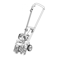
INSTALLING THE WHEEL ASSEMBLY
See Figures 3 - 4.
Use the wheel assembly accessory to transport the unit to
and from the work area.
To install:
Remove the adjustment knob located at the back of the
tine shield.
Insert the wheel assembly support rod into the opening
beneath the adjustment knob. To place the wheels in a
high position, insert the rod to the first hole. For a lower
wheel position, insert the rod to the second or third hole.
Rotate the adjustment knob in the opposite direction
to return it to the seated position, which will secure the
wheel assembly in place.
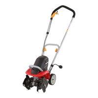
ASSEMBLY
 Loading...