Do you have a question about the Honda 2005 FOURTRAX FOREMAN TRX500 TM and is the answer not in the manual?
Information for qualified technicians on service and repair procedures, including warnings.
Emphasizes the importance of proper service for customer safety and vehicle reliability.
Warns untrained individuals against attempting procedures described in the manual.
General safety practices like reading instructions, using protective gear, and securing the vehicle.
Details about safety alert symbols (DANGER, WARNING, CAUTION) and notices used in the manual.
Guidelines for using genuine parts, tools, and proper service procedures to avoid damage.
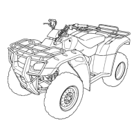
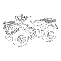
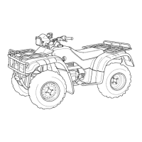
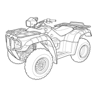
Key technical data and measurements for the vehicle, including dimensions and weight.
Crucial fastener torque specifications for assembly and maintenance tasks.
Identifies specific locations and materials for lubrication and sealing procedures.
Explains the integration of various control units into the ECM for cost reduction and space conservation.
Illustrates and lists the locations of major body panels on the vehicle for identification.
Specifies torque values for frame, body panels, and exhaust system fasteners.
Procedures for removing, installing, and disassembling the exhaust system components.
Outlines routine maintenance intervals and tasks based on mileage or time.
Steps for inspecting and adjusting valve clearance on a cold engine.
Procedures for checking and changing engine oil, including level check and capacity.
Instructions for replacing and bleeding brake fluid, including safety notes.
Explains the flow of oil throughout the lubrication system for better understanding.
Details on the removal, disassembly, assembly, and installation of the oil pump.
Procedures for removing, disassembling, assembling, and installing the cooling fan.
Lists common fuel system problems and their probable causes for diagnosis.
Step-by-step instructions for removing the carburetor assembly from the vehicle.
Exploded view and procedures for assembling the carburetor components correctly.
Detailed steps for adjusting the pilot screw for proper idle drop.
Detailed steps and precautions for removing the engine from the vehicle frame.
Procedures for reinstalling the engine, including routing wires and tightening bolts.
Procedure for testing cylinder compression and interpreting results.
Step-by-step guide for removing the cylinder head assembly.
Instructions for replacing valve guides, including heating and chilling procedures.
Methods for inspecting and refacing valve seats for proper sealing.
Procedure for removing the cylinder, emphasizing care to avoid damage.
Steps for removing the piston, including handling the pin and clips.
How to measure cylinder bore for wear, taper, and out-of-round.
Inspecting piston rings for smooth movement and measuring clearances.
Lists common clutch and gearshift problems and their solutions.
Steps for removing the centrifugal clutch assembly.
How to inspect and measure clutch disc thickness and check for damage.
Procedures for removing and inspecting the gearshift linkage components.
Steps to remove the recoil starter assembly, including rope replacement.
Procedures for removing and inspecting the alternator stator.
How to remove the flywheel and starter driven gear assembly.
Detailed steps for disassembling the starter clutch components.
Steps for separating the crankcase halves to access internal components.
Procedures for disassembling the transmission components.
How to measure crankshaft runout and inspect balancer gears.
Detailed steps for cleaning, sealing, and assembling the crankcase halves.
Specifications for tightening various bolts and nuts in the front suspension and steering.
Common issues related to steering, wheel wobble, suspension, and noise.
Steps to remove the handlebar assembly, including switches and levers.
Procedures for removing the front wheel, including loosening nuts and lifting the vehicle.
Instructions for repairing tire punctures using plugs and patches.
Steps to remove the wheel hub and knuckle assembly.
Procedures for replacing ball joints using special tools.
Removal and inspection of the steering shaft and its components.
Torque specifications for rear wheel, shock absorber, and swingarm mounting points.
Common problems related to rear wheel wobble, stiffness, noise, and oil leaks.
Steps for removing the rear wheel, including loosening nuts and lifting the vehicle.
How to remove the rear shock absorber assembly.
Procedures for removing the swingarm and its associated components.
Detailed steps for draining, filling, and bleeding the brake fluid system.
How to inspect brake pads for wear and the brake disc for damage or warpage.
Procedures for disassembling the front brake caliper, including pad and piston removal.
Steps for disassembling the rear brake drum, including shoe and spring removal.
Steps to remove the front drive shaft, including handling the stopper ring.
Procedures for disassembling and inspecting the front final gear components.
How to measure gear backlash and adjust using shims.
Steps for removing the differential assembly and its shims.
Procedures for removing the pinion gear and its bearing.
Steps for removing the rear axle, including brake components and housing.
How to measure axle runout using a dial indicator.
Procedures for removing the final drive assembly and related parts.
Measuring ring gear backlash and adjusting with shims.
Using Prussian Blue to check gear tooth contact patterns for proper meshing.
Steps to remove the pinion gear, including the lock nut and bearing.
Visual representation of the battery and charging system electrical connections.
Procedures for testing battery condition using a recommended tester.
Instructions for safely charging the battery, including settings and precautions.
How to measure charging voltage to diagnose system health.
Diagnoses for no spark at the plug and related issues.
Procedure to measure the primary peak voltage from the ignition coil.
Steps to measure peak voltage from the ignition pulse generator.
How to check and adjust ignition timing using a timing light.
Diagnoses for starter motor not turning, turning slowly, or not engaging the engine.
Procedures for removing the starter motor, including disconnecting cables.
Checks for proper operation, circuit continuity, and function of the starter relay.
Steps for replacing the headlight bulb and cover.
How to check power, ground, and continuity for the accessory socket.
Checking continuity of the ignition switch in different positions.
Checking continuity of various handlebar-mounted switches.
Verifying continuity for each gear position to ensure proper function.
Guides for diagnosing and resolving issues with the electric shift system.
How to access and clear diagnostic trouble codes from the ECM.
Procedures for checking angle sensor resistance and input voltage.
Steps for removing, inspecting, and installing the control motor and reduction gears.
Electrical diagram showing the components of the 4WD system.
Table linking 4WD indicator blink codes to potential issues and reference pages.
Diagnostic steps for the front vehicle speed sensor.
Diagnostic steps for the rear vehicle speed sensor.
Troubleshooting steps for issues with the front final clutch.
Wiring diagram specific to the A/CM type TM model.
Wiring diagram for the U-type TM model.
Wiring diagram for the FM model.
Wiring diagram for the FE model.
Diagnostic steps for starting issues, including fuel flow, spark, and compression.
Troubleshooting steps when the engine lacks power, covering drive train, tires, clutch, and ignition.
Steps to diagnose and fix poor performance at low engine speeds.
Troubleshooting for issues affecting high-speed performance.
| Brand | Honda |
|---|---|
| Model | 2005 FOURTRAX FOREMAN TRX500 TM |
| Category | Offroad Vehicle |
| Language | English |