

S
Stacey AndersonJul 28, 2025
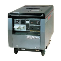
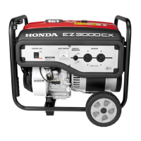
What to do if my Honda EZ3000CX Inverter engine will not start?
- CCrystal DelacruzJul 29, 2025
If your Honda Inverter's engine won't start, you can try a few things. First, refill the fuel tank. If that doesn't work, replace the spark plug. You can also try cleaning the fuel sediment cup. If none of these steps work, take the generator to an authorized dealer.