EasyManua.ls Logo

Honda GX200 User Manual

Honda GX200
133 pages
To Next Page IconTo Next Page
Page #1 background imageLoading...
Page #1 background image
0
dummyheaddummyhead
How to use this manual
A Few Words About Safety
Service Information
The service and repair information contained in this manual is intended for use by qualified, professional technicians. Attempting
service or repairs without the proper training, tools, and equipment could cause injury to you and/or others. It could also damage
this Honda product or create an unsafe condition.
This manual describes the proper methods and procedures
for performing service, maintenance, and repairs. Some procedures
require the use special tools. Any person who intends to use a replacement part, service procedure, or a tool that is not
recommended by Honda must determine the risks to their personal safety and the safe operation of this product.
If you need to replace a part, use Honda Genuine parts with the correct part number or an equivalent part. We strongly recommend
that you do not use replacement parts of inferior quality.
For Your Customer’s Safety
Proper service and maintenance are essential to the customer’s safety and the reliability of this product. Any error or oversight
while servicing this product can result in faulty operation, damage to the product, or injury to others.
For Your Safety
Because this manual is intended for the professional service technician, we do not provide warnings about many basic shop safety
practices (e.g., Hot parts-wear gloves). If you have not received shop safety training or do not feel confident about your knowledge
of safe servicing practices, we recommend that you do not attempt to perform the procedures described in this manual.
Some of the most important general service safety precautions are given below. Ho
wever, we cannot warn you of every
conceivable hazard that can arise in performing service and repair procedures. Only you can decide whether or not you should
perform a given task.
Important Safety Precautions
Make sure you have a clear understanding of all basic shop safety practices and that you are wearing appropriate clothing and
using safety equipment. When performing any service task, be especially careful of the following:
Read all of the instructions before you begi
n, and make sure you have the tools, the replacement or repair parts, and the skills
required to perform the tasks safely and completely.
Protect your eyes by using proper safety glasse
s, goggles, or face
shields anytime you hammer, drill, grind, or work around
pressurized air, pressurized liquids, springs or other stored-energy components. If there is any doubt, put on eye protection.
Use other protective wear when necessary, for example gloves or safety shoes. Handling hot or sharp parts can cause severe
burns or cuts. Before you grab something that looks like it can hurt you, stop and put on gloves.
Protect yourself and others whenever you have equipment hoisted in the air. Anytime you lift this product with a hoist, make sure
that the hoist hook is securely attached to the product.
Make sure the engine is off before you begin any servicing procedures, unless the instruction tells you to do otherwise. This will
help eliminate several potential hazards:
Carbon monoxide poisoning from engine exhaust. Be sure there is adequate ventilation whenever you run the engine.
Burns from hot parts. Let the engine and exhaust system cool before wo
rking in those areas.
Injury from moving parts. If the instruction tells you to run the engine, be sure your hands, fingers, and clothing are out of the
way.
Gasoline vapors and hydrogen gasses from batteries are explosive. To reduce the possibility of a fire or explosion, be careful when
working around gasoline or batteries.
Use only a nonflammable solvent, not gasoline, to clean parts.
Never store gasoline in an open container.
Keep all cigarettes, sparks, and flames away from the battery and all fuel-related parts.
Improper service or repairs can create an unsafe
condition that can cause your customer or others to
be seriously hurt or killed.
Follow the procedures and precautions in this
manual and other service materials carefully.
Failure to properly follow instructions and
precautions can cause you to be seriously hurt or
killed.
Follow the procedures and precautions in this
manual carefully.
gx120k1_gx160k1_gx200

Other manuals for Honda GX200

Question and Answer IconNeed help?

Do you have a question about the Honda GX200 and is the answer not in the manual?

Honda GX200 Specifications

General IconGeneral
Bore x Stroke68 mm x 54 mm
Compression Ratio8.5:1
PTO Shaft RotationCounterclockwise (from PTO shaft side)
Ignition SystemTransistorized magneto ignition
Lubrication SystemSplash
Dry Weight16.0 kg (35.3 lbs)
Engine TypeAir-cooled 4-stroke OHV single cylinder
Displacement196 cm³
Net Power Output5.5 HP (4.1 kW) at 3600 rpm
Fuel Tank Capacity3.1 L (0.82 US gal)
Starting SystemRecoil
Air CleanerDual element
Oil Capacity0.6 L (0.63 US qt)
Net Torque12.4 Nm (9.1 lb-ft) at 2, 500 rpm

Summary

About This Manual

Safety Information

General safety advice and precautions for handling the product.

Service Rules and Symbols

Essential rules for performing service and explanation of symbols used in the manual.

Abbreviations Used

A list of abbreviations and their full terms used throughout the manual.

Specifications

Model Specifications Overview

Detailed technical specifications for engine models, including power, dimensions, and capacities.

Dimensions and Weights

Model-Specific Dimensions

Tables detailing length, width, height, and weight for different engine models and types.

Performance Curves

Engine Performance Data

Graphical representation of engine torque and net power output versus engine speed.

Dimensional Drawings

Engine Dimensional Drawings

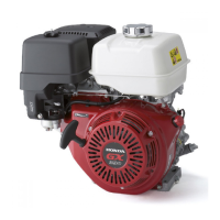
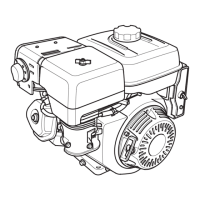
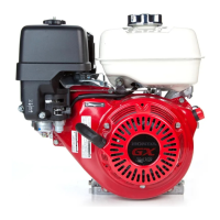
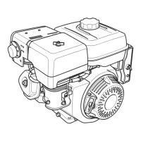
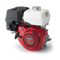
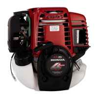
Visual representations of engine models with key dimensions indicated.

PTO Shaft Drawings

Detailed drawings of the Power Take-Off (PTO) shaft dimensions for various configurations.

Wiring Diagrams

Starter and Charging System Diagrams

Diagrams illustrating the electrical connections for starter and charging systems.

Service Information

Maintenance Standards and Limits

Specifications for engine part measurements and acceptable service limits.

Torque Values and Tools

Recommended torque specifications and lists of required service tools.

Troubleshooting Engine Issues

Step-by-step diagnostic procedures for common engine operational problems.

Maintenance

Maintenance Schedule and Engine Oil

Recommended service intervals and procedures for engine oil checks and changes.

Air Cleaner and Carburetor Service

Instructions for maintaining the air cleaner and servicing the engine carburetor.

Spark Plug and Valve Clearance

Procedures for inspecting and adjusting spark plugs and valve clearances.

Air Cleaner and Muffler

Air Cleaner Service Procedures

Detailed instructions for disassembling, cleaning, and reassembling various air cleaner types.

Muffler Disassembly and Reassembly

Procedures for removing, cleaning, and reinstalling the engine muffler.

Recoil Starter and Fan Cover

Recoil Starter Service

Instructions for the disassembly, reassembly, and inspection of the recoil starter mechanism.

Fan Cover and Control Box Service

Procedures for servicing the fan cover, control box, and associated electrical components.

Carburetor

Carburetor Removal, Installation, and Cleaning

Steps for servicing the carburetor, including removal, installation, and cleaning procedures.

Pilot Screw and Limiter Cap Service

Instructions for adjusting the pilot screw and servicing the limiter cap on the carburetor.

Fuel Tank, Governor, and Control Base

Fuel Tank System Service

Instructions for servicing the fuel tank, fuel filter, and fuel cap assembly.

Governor Arm Adjustment

Steps to adjust the governor arm for proper engine speed control.

Flywheel, Ignition Coil, and Starter Motor

Flywheel and Ignition Coil Service

Procedures for inspecting and adjusting the flywheel and ignition coil components.

Starter Motor Components Service

Steps for disassembling, inspecting, and testing the starter motor and its components.

Cylinder Head and Valves

Cylinder Head Service

Instructions for removing, installing, and servicing the cylinder head and its components.

Valve System Service

Detailed steps for valve disassembly, guide replacement, and seat reconditioning.

Crankshaft, Piston, and Related Components

Crankshaft and Piston Assembly Service

Procedures for disassembling and reassembling the crankshaft, piston, and related components.

Piston Ring and Clearance Service

Instructions for piston ring reassembly, inspection, and measurement of clearances.

Governor and Oil Level Switch

Governor Mechanism and Oil Level Switch Service

Procedures for servicing the governor mechanism and inspecting the oil level switch.

Reduction Unit

Reduction Unit Types and Service

Explains different reduction unit types and their disassembly/reassembly procedures.

Clutch System Inspection

Methods for inspecting clutch friction disc thickness and plate warpage.

Optional Parts and Kits

Lamp Coil Kits

Information on available lamp coil kits and their power output configurations.

Remote Control Kits

Details on installing remote control kits for choke and throttle functions.

Related product manuals