EasyManua.ls Logo

Honda HRN216PKC User Manual

Honda HRN216PKC
215 pages
To Next Page IconTo Next Page
Page #1 background imageLoading...
Page #1 background image
A Few Words About Safety
SERVICE INFORMATION
The service and repair information contained in this manual is intended for use by qualified, professional technicians. Attempting
service or repairs without the proper training, tools, and equipment could cause injury to you and/or others. It could also damage
this Honda product or create an unsafe condition.
This manual describes the proper methods and procedures for performing service, maintenance, and repairs. Some procedures
require the use of special tools. Any person who intends to use a replacement part, service procedure, or a tool that is not
recommended by Honda must determine the risks to his or her personal safety and the safe operation of this product.
If you need to replace a part, use Honda Genuine parts with the correct part number or an equivalent part. We strongly recommend
that you do not use replacement parts of inferior quality.
For Your Customer’s Safety
Proper service and maintenance are essential to the customer’s safety and the reliability of this product. Any error or oversight
while servicing this product can result in faulty operation, damage to the product, or injury to others.
For Your Safety
Because this manual is intended for the professional service technician, we do not provide warnings about many basic shop safety
practices (Hot parts-wear gloves, for example). If you have not received shop safety training or do not feel confident about your
knowledge of safe servicing practice, we recommend that you do not attempt to perform the procedures described in this manual.
Some of the most important general service safety precautions are given below. However, we cannot warn you of every
conceivable hazard that can arise in performing service and repair procedures. Only you can decide whether or not you should
perform a given task.
Important Safety Precautions
Make sure you have a clear understanding of all basic shop safety practices and that you are wearing appropriate clothing and
using safety equipment. When performing any service task, be especially careful of the following:
Read all of the instructions before you begin, and make sure you have the tools, the replacement or repair parts, and the skills
required to perform the tasks safely and completely.
Protect your eyes by using proper safety glasses, goggles, or face shields anytime you hammer, drill, grind, or work around
pressurized air, pressurized liquids, springs or other stored-energy components. If there is any doubt, put on eye protection.
Use other protective wear when necessary, for example gloves or safety shoes. Handling hot or sharp parts can cause severe
burns or cuts. Before you grab something that looks like it can hurt you, stop and put on gloves.
Protect yourself and others whenever you have engine-power equipment up in the air. Anytime you lift this product with a hoist,
make sure that the hoist hook is securely attached to the product.
Make sure the engine is off before you begin any servicing procedures, unless the instruction tells you to do otherwise. This will
help eliminate several potential hazards:
Carbon monoxide poisoning from engine exhaust. Be sure there is adequate ventilation whenever you run the engine.
Burns from hot parts. Let the engine and exhaust system cool before working in those areas.
Injury from moving parts. If the instruction tells you to run the engine, be sure your hands, fingers and clothing are out of the way.
Gasoline vapors and hydrogen gasses from battery are explosive. To reduce the possibility of a fire or explosion, be careful when
working around gasoline or batteries.
Use only a nonflammable solvent, not gasoline, to clean parts.
Never store gasoline in an open container.
Keep all cigarettes, sparks, and flames away from the battery and all fuel-related parts.
Improper service or repairs can create an
unsafe condition that can cause your customer
or others to be seriously hurt or killed.
Follow the procedures and precautions in this
manual and other service materials carefully.
Failure to properly follow instructions and
precautions can cause you to be seriously hurt
or killed.
Follow the procedures and precautions in this
manual carefully.

Table of Contents

Question and Answer IconNeed help?

Do you have a question about the Honda HRN216PKC and is the answer not in the manual?

Honda HRN216PKC Specifications

General IconGeneral
EngineHonda GCV170
Engine Displacement170 cc
Cutting Width21 inches
Starter TypeRecoil
Weight77 lbs
Deck MaterialSteel
HandleFolding
Mulching CapabilityYes
Bagging CapabilityYes
Cutting Height Adjustments7 positions
Warranty3 years
Cutting Height Range1.1 - 4 in
Fuel Tank Capacity0.24 gal
DischargeSide
Cutting Height Adjustment6 Positions
Blade TypeTwin blades

Summary

A Few Words About Safety

SERVICE INFORMATION

General information regarding service and repair procedures for qualified technicians.

For Your Customer’s Safety

Emphasizes the importance of proper service for customer safety and product reliability.

For Your Safety

Highlights general service safety precautions and the user's responsibility for hazard assessment.

Important Safety Precautions

Lists essential safety practices and precautions to follow before and during service tasks.

INTRODUCTION

SAFETY MESSAGES

Explains the purpose and meaning of safety alert symbols and signal words used in the manual.

LAWN MOWER TYPE IDENTIFICATION

Quick Identifier

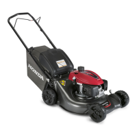
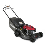
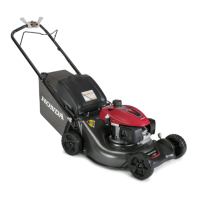
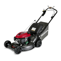
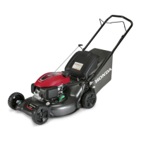
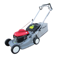
Provides a table and images to quickly identify different HRN216 mower types.

1. SPECIFICATIONS

1. SPECIFICATIONS

DIMENSIONS, WEIGHTS, AND CAPACITIES

Details physical specifications including dimensions, weight, and fluid capacities for different models.

ENGINE

Lists detailed specifications for the engine, including model, type, displacement, and ignition system.

DRIVETRAIN

Provides specifications related to the drivetrain, such as ground speed and transmission type.

2. DIMENSIONAL DRAWINGS

3. WIRING DIAGRAM (VLA TYPE)

2. SERVICE INFORMATION

1. SERVICE RULES

Outlines essential rules and guidelines for performing service and repairs.

2. SYMBOLS USED IN THIS MANUAL

Explains the meaning of symbols used throughout the manual to indicate special tools or procedures.

3. SERIAL NUMBER LOCATIONS

4. SERVICE SPECIFICATIONS

5. TORQUE VALUES

STANDARD TORQUE VALUES

6. TOOLS

Lists special tools required for maintenance and repair procedures.

7. TROUBLESHOOTING

ENGINE

Provides troubleshooting steps for engine starting and performance issues.

VIBRATION PROBLEMS

DRIVE SYSTEM (VKA/VLA/VYA TYPES)

Troubleshooting steps for drive system issues like mower not self-propelling or slipping.

8. TROUBLESHOOTING TECHNIQUES

COMPRESSION TEST

Detailed procedure for measuring cylinder compression using a gauge.

SPARK PLUG TEST

Procedure for checking the spark plug for proper operation.

CRANKSHAFT RUNOUT INSPECTION

CHOKE CONTROL SYSTEM

CHARGE COIL OUTPUT CHECK

ENGINE STOP SWITCH SYSTEM INSPECTION

Procedure to inspect the continuity and operation of the engine stop switch system.

SMART DRIVE TRANSMISSION

1. MOWER WILL NOT SELF-PROPEL WHEN THE SMART DRIVE IS ENGAGED

Troubleshooting steps when the mower fails to self-propel with Smart Drive engaged.

2. TRANSMISSION PROPELS THE MOWER, BUT SLIPS OR SLOWS DOWN UNDER LOAD

Troubleshooting steps for transmission slipping or slowing down under load.

4. ONLY ONE WHEEL PROPELS OR ONE WHEEL INTERMITTENTLY STOPS ROTATING UNDER LOAD

5. TRANSMISSION LEAKS OIL

Troubleshooting steps for identifying and fixing transmission oil leaks.

9. CABLE ROUTING AND TIES

PKA TYPE

Instructions for routing cables and ties on the handlebar for PKA type mowers.

VKA TYPE

VLA TYPE

VYA TYPE

10. TUBE AND HARNESS ROUTING

PKA/VKA/VLA TYPES

Procedure for routing breather and fuel tubes for PKA, VKA, and VLA mower types.

3. MAINTENANCE

1. MAINTENANCE SCHEDULE

2. MAINTENANCE SPECIFICATIONS

3. ENGINE TUNE-UP SPECIFICATIONS

Specifications for engine tune-up procedures like spark plug gap and valve clearance.

4. REAR SHIELD

Guidance on checking and replacing the rear shield for deterioration and wear.

5. BLADES

INSPECTION

Procedure for inspecting blades for damage, cracks, and excessive wear.

REMOVAL/INSTALLATION

Step-by-step instructions for removing and installing mower blades.

SHARPENING

6. ENGINE OIL

7. AIR FILTER CLEANING

8. GRASS BAG

9. SPARK PLUG INSPECTION

Procedure for inspecting the spark plug, including gap measurement and replacement.

10. SPARK ARRESTER CLEANING

11. COMBUSTION CHAMBER CLEANING

Procedure for cleaning the engine's combustion chamber.

12. SMART DRIVE CABLE

VKA/VLA/VYA TYPES ONLY

Specific instructions for Smart Drive cable adjustment applicable to VKA, VLA, and VYA models.

CABLE ADJUSTMENT

Detailed steps for adjusting the Smart Drive cable for proper mower operation.

14. BLADE CONTROL OPERATION CHECK

FLYWHEEL BRAKE MODELS

Procedure to check blade control operation on models equipped with a flywheel brake.

ROTO-STOP®

Procedure to check blade control operation for Roto-Stop equipped models.

15. FLYWHEEL BRAKE

INSPECTION

Procedure for inspecting the thickness of the flywheel brake lining.

17. THROTTLE CABLE AND LINKAGE

VYA TYPE ONLY

Specific instructions for throttle cable and linkage adjustment for VYA type mowers.

18. VALVE CLEARANCE

19. PINION GEAR

LUBRICATION

Instructions for lubricating the pinion gear assembly.

DISASSEMBLY

Steps for disassembling the pinion gear assembly.

REASSEMBLY

20. GOVERNOR

PKA, VKA, VLA TYPES

Procedure for adjusting the governor on PKA, VKA, and VLA mower types.

ADJUSTMENT

Detailed steps for adjusting the governor arm and engine speed.

VYA TYPE

4. BLADE HOLDER/ROTO-STOP®

1. BLADE HOLDER/DRIVE PULLEY

PKA TYPE

Details for the blade holder and drive pulley specific to the PKA mower type.

REMOVAL

INSTALLATION

Procedure for installing the blade holder assembly.

VKA/VLA TYPES

REMOVAL

INSTALLATION

Procedure for installing the blade holder assembly for VKA, VLA, and VYA types.

2. ROTO-STOP®/DRIVE PULLEY

VYA TYPE

Details for the Roto-Stop and drive pulley specific to the VYA mower type.

PARTS REFERENCE

Visual reference of parts for the Roto-Stop and drive pulley assembly.

REMOVAL

INSPECTION

3. Disassemble the brake assembly:

5. Measure the clutch spring free-standing height:

8. Assemble the brake (it is not necessary to apply any lubrication to any of the Roto-Stop parts during assembly):

INSTALLATION

Procedure for installing the Roto-Stop brake assembly.

2. Align the drive disk keyway with the key, and install the drive disk.

5. Attach the Roto-Stop cable to the ball plate.

5. ENGINE REMOVAL/INSTALLATION

1. PKA/VKA TYPES

REMOVAL

Steps for removing the engine from PKA and VKA type mowers.

INSTALLATION

2. VLA TYPE

REMOVAL

Steps for removing the engine from VLA type mowers.

INSTALLATION

3. VYA TYPE

REMOVAL

Steps for removing the engine from VYA type mowers.

INSTALLATION

6. MUFFLER

1. REMOVAL/INSTALLATION

7. RECOIL STARTER

1. TOP COVER REMOVAL/INSTALLATION

Procedure for removing and installing the recoil starter top cover.

2. RECOIL REMOVAL/INSTALLATION

3. FAN COVER REMOVAL/INSTALLATION

4. RECOIL STARTER INSPECTION

5. RECOIL STARTER ROPE REPLACEMENT

Procedure for replacing the recoil starter rope.

6. REEL UNWOUND

8. FUEL SYSTEM

1. AIR CLEANER/CARBURETOR

REMOVAL/INSTALLATION

Steps for removing and installing the air cleaner and carburetor.

DISASSEMBLY/REASSEMBLY

INSPECTION

FLOAT LEVEL HEIGHT

Procedure for measuring and checking the float level height.

PILOT SCREW AND LIMITER CAP REPLACEMENT

Procedure for replacing the pilot screw and limiter cap.

CLEANING

CHOKE CONTROL ASSEMBLY

Thermowax Removal

Steps for removing the thermowax from the choke control assembly.

Thermowax Installation

2. CONTROL BASE/GOVERNOR ARM

PKA/VKA/VLA TYPES

Control base and governor arm removal/installation for PKA, VKA, VLA types.

REMOVAL/INSTALLATION

Steps for removing and installing the control base and governor arm.

VYA TYPE

3. FUEL TANK

DISASSEMBLY/REASSEMBLY

Procedure for disassembling and reassembling the fuel tank.

4. FUEL TUBE

REMOVAL/INSTALLATION

Steps for removing and installing the fuel tube.

9. IGNITION COIL/FLYWHEEL

1. IGNITION COIL

REMOVAL/INSTALLATION

Procedure for removing and installing the ignition coil for PKA/VKA types.

PKA/VKA TYPES

Specific instructions for ignition coil removal/installation on PKA/VKA models.

VLA TYPE

VYA TYPE

SPARK TEST

INSPECTION

Inspection of ignition coil primary and secondary side resistance.

Engine Stop Switch

PKA/VKA/VLA TYPES

Inspection of engine stop switch for PKA, VKA, VLA types.

VYA TYPE

Inspection of engine stop switch for VYA type.

IGNITION COIL AIR GAP ADJUSTMENT

Procedure for adjusting the air gap between the ignition coil and flywheel.

CHARGE COIL AND DIODE TEST

2. FLYWHEEL

DISASSEMBLY/REASSEMBLY

Steps for disassembling and reassembling the flywheel.

FLYWHEEL REMOVAL

INSTALLATION

3. FLYWHEEL BRAKE LEVER / ENGINE STOP SWITCH

4. ELECTRIC STARTER (VLA TYPE)

STARTER MOTOR VOLTAGE INSPECTION

Procedure for inspecting the starter motor voltage.

STARTER MOTOR REMOVAL/INSTALLATION

Steps for removing and installing the starter motor.

STARTER MAGNETIC SWITCH INSPECTION

STARTER MAGNETIC SWITCH REMOVAL/INSTALLATION

STARTER MOTOR INSPECTION

Inspection of starter motor components, including pinion gear.

Pinion Gear

Inspection of the starter motor pinion gear for wear and damage.

CLEANING AND INSPECTING THE PINION DAMPER ASSEMBLY

Procedure for cleaning and inspecting the pinion damper assembly.

2. FRONT COVER

FRONT COVER REMOVAL/INSTALLATION

REMOVAL

Steps for removing the front cover assembly from the mower deck.

INSTALLATION

3. CUTTER HOUSING

REMOVAL

Steps for removing the cutter housing.

HANDLEBAR STAYS

REMOVAL

Procedure for removing the handlebar stays from the mower deck.

INSTALLATION

Procedure for installing the handlebar stays onto the mower deck.

4. REAR HOUSING

PARTS IDENTIFICATION

Identification of parts related to the rear housing assembly.

REMOVAL

VKA/VLA types:

Removal steps for VKA and VLA type mowers, including blades and drive belt.

VYA type:

Removal steps for VYA type mowers, including blades and drive belt.

3. Remove the handlebar and both handlebar stays as an assembly.

5. Remove the four 6 mm flange bolts attaching the rear housing from the metal mower deck, and then slide the rear housing away from the deck.

8. Remove the discharge guard by driving out the metal shaft from one side.

INSTALLATION

Installation steps for the rear housing assembly.

5. REAR SHIELD

REMOVAL

Steps for removing the rear shield.

INSTALLATION

13. TRANSMISSION/DRIVE BELT

1. TRANSMISSION/DRIVE BELT

Procedures for transmission and drive belt maintenance for VKA, VLA, VYA types.

VKA/VLA TYPES

Specific removal steps for the transmission and drive belt on VKA/VLA models.

REMOVAL

Detailed steps for removing the transmission and drive belt assembly.

8. Push down on the transmission control arm (against spring tension), and disconnect the Smart Drive cable from the transmission control arm.

INSTALLATION

VYA TYPE

REMOVAL

Specific removal steps for the transmission and drive belt on VYA models.

5. Disconnect the Roto-Stop return spring and then remove the lower end of Roto-Stop cable (P. 4-2).

9. Turn the mower upside down and rest the handlebar on a workbench.

INSTALLATION

2. DISASSEMBLY/REASSEMBLY

PINION GEAR

Procedure for disassembling and reassembling the pinion gear.

AXLE SHAFT

TRANSMISSION

Related product manuals