Do you have a question about the Honda WT30XK4 and is the answer not in the manual?
General safety precautions and warnings for using the manual and performing service.
Guidelines and rules to follow when servicing the product.
Explanation of symbols used throughout the manual for service procedures.
List of common abbreviations used in the manual for parts and systems.
Explains the use of safety alert symbols, signal words (DANGER, WARNING, CAUTION), and instructions.
Locates the engine and frame serial numbers for inquiries and parts ordering.
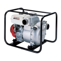
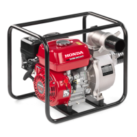
Details dimensions, weights, engine, and water pump specifications.
Presents graphical data illustrating pump performance under various conditions.
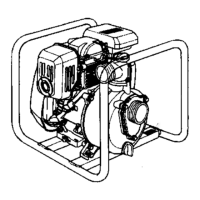
Provides detailed illustrations of product dimensions for reference.
Lists standard measurements and service limits for various engine and pump components.
Provides specific torque values for engine, water pump, and standard fasteners.
Details lubrication and sealing points for engine and water pump components.
Lists special tools required for service procedures with part numbers.
Lists common tools available commercially that can be used for service.
Illustrates the correct routing of wiring harnesses and tubes for proper assembly.
Outlines the recommended maintenance intervals for engine and pump components.
Instructions for checking and changing the engine oil, including recommended oil type.
Procedures for inspecting, cleaning, or replacing the air cleaner element.
Steps for safely cleaning the sediment cup to ensure proper fuel flow.
Guide for inspecting, adjusting gap, or replacing the spark plug for optimal ignition.
Instructions for cleaning the spark arrester to maintain exhaust system performance.
Steps to check and adjust the engine idle speed for stable operation.
Procedure for checking and adjusting valve clearance to ensure proper engine timing.
Steps to remove carbon deposits from the combustion chamber for better performance.
Instructions for cleaning the fuel tank and filter to ensure a clean fuel supply.
Guide for inspecting the fuel tube for any signs of deterioration or leakage.
Procedure for inspecting the pump impeller for damage or contamination.
How to measure and adjust the clearance between the impeller and the volute case.
Steps to check the pump inlet valve for proper operation and condition.
Initial checks and preparation steps before diagnosing problems.
Diagnoses and solutions for common engine problems like being locked up or not starting.
Procedures to diagnose and resolve an engine that cannot be rotated.
Step-by-step guide to troubleshoot why the engine fails to start.
Troubleshooting steps for an engine that is surging or running erratically.
Diagnoses for why the engine fails to stop when the stop switch is activated.
Troubleshooting for the engine not stopping due to low oil level switch issues.
Diagnoses and solutions for common water pump problems.
Steps to troubleshoot why the water pump fails to prime and draw fluid.
Diagnoses for low water discharge volume or pressure from the pump.
Troubleshooting steps for noise or vibration caused by pump cavitation.
Instructions for removing and installing the fan cover assembly.
Lists necessary tools for fuel system maintenance and repairs.
Procedures for removing and installing the fuel tank and related components.
Details on removing and installing the fuel filter holder for AC type models.
Guide for removing and installing the air cleaner assembly.
Steps for removing and installing the carburetor for maintenance.
Detailed instructions for disassembling and reassembling the carburetor.
Procedures for cleaning the internal passages and ports of the carburetor body.
Guide for inspecting the carburetor, including float level height.
Steps for replacing the pilot screw and limiter cap for fuel mixture control.
Instructions for replacing the choke valve plate and shaft in the carburetor.
Procedure for replacing the cylinder stud bolts.
Instructions for removing and installing the governor arm and control base assembly.
Steps for disassembling and reassembling the control base of the governor system.
Guide for adjusting the engine's maximum speed using the governor system.
Lists specific tools required for ignition system service.
Provides a schematic diagram of the ignition system wiring.
Troubleshooting steps for common ignition system problems, focusing on no spark.
Detailed troubleshooting flow for diagnosing and resolving a lack of spark.
Procedures for removing and installing the cooling fan and flywheel.
Instructions for removing and installing the ignition coil.
Method for testing for spark presence and quality to diagnose ignition issues.
Procedure for inspecting the spark plug cap for resistance and continuity.
Steps for measuring ignition coil resistance to check its functionality.
How to inspect the oil level switch for proper operation and continuity.
Procedure for checking the engine stop switch continuity in different positions.
Steps for removing and installing the recoil starter assembly.
Detailed instructions for disassembling and reassembling the recoil starter mechanism.
How to inspect the recoil starter operation and pulley for damage.
Lists the vacuum gauge used for pump testing.
Instructions for removing and installing the pump's front cover.
Procedures for removing and installing the pump casing.
Steps for disassembling and reassembling the pump's front cover.
Instructions for disassembling and reassembling the pump casing.
Procedure for performing a vacuum test to check pump sealing and performance.
Steps for safely removing and installing the engine from the frame.
Lists specific tools required for cylinder head and valve service.
Procedures for removing and installing the cylinder head.
Detailed steps for disassembling and reassembling the cylinder head components.
Methods for inspecting cylinder compression, head warpage, and valve seats.
How to measure the inner diameter of the valve guides.
Instructions for inspecting the valve face for irregularities.
Procedure for measuring the outer diameter of the valve stem.
How to calculate and check the clearance between the valve stem and guide.
Method for measuring the free length of the valve spring.
How to measure the perpendicularity of the valve spring.
Instructions for checking the push rod for wear and straightness.
Detailed procedure for replacing valve guides, including heating the cylinder head.
Steps for reaming valve guides to ensure proper fit and alignment.
Procedures for cleaning, lapping, and resurfacing valve seats.
Lists specific tools required for crankcase service and repairs.
Instructions for removing and installing the crankcase cover.
Procedures for removing and installing the crankshaft, balancer, and piston assembly.
Steps for installing the balancer weight and camshaft with timing marks.
Instructions for disassembling and reassembling the governor components.
Detailed guide for disassembling and assembling the piston, rings, and connecting rod.
Procedures for inspecting critical internal engine components for wear.
How to measure the piston skirt outside diameter for wear.
Steps to measure and check the clearance between the piston and cylinder sleeve.
Procedure for measuring the inner diameter of the piston pin bore.
How to measure the outer diameter of the piston pin.
Steps to measure and check the clearance between the piston pin and its bore.
How to measure the side clearance of piston rings in their grooves.
Procedure for measuring the width of the piston rings.
Steps to measure the end gap of the piston rings.
How to measure the side clearance of the connecting rod's big end.
Procedure for measuring the inner diameter of the connecting rod's small end.
Steps to measure the inner diameter of the connecting rod's big end.
How to measure the outer diameter of the crankshaft's crank pin.
Procedure using Plastigauge to measure oil clearance for the connecting rod big end.
How to measure crankshaft runout using V-blocks and a dial indicator.
Procedure for measuring the cam height of the camshaft.
How to measure the outer diameter of the camshaft.
Check for wear on the decompressor weight and its spring.
Instructions for replacing crankshaft bearings on the crankshaft side.
Procedures for replacing bearings and oil seals on the cylinder barrel side.
Specific instructions for replacing the balancer weight bearing.
Procedure for replacing the governor arm shaft oil seal.
Instructions for removing and installing the muffler assembly.
Procedure for replacing exhaust pipe stud bolts.
Provides a schematic of the engine's electrical wiring for troubleshooting and reference.
| Pump Type | Centrifugal |
|---|---|
| Fuel Type | Unleaded gasoline |
| Starting System | Recoil start |
| Max Output | 3, 600 rpm |
| Max Flow Rate | 317 GPM |
| Max Head | 85 ft (26 m) |
| Inlet/Outlet Size | 80 mm / 80 mm |
| Suction Head Lift | 26 ft |
| Oil Capacity | 0.6 liters |