Testing Operation7
Install Batteries and Cover
6
Install Exterior Assembly3 Install Interior Assembly4
Install Interior Assembly
5
1
Installation Overview
Install Enclosed Latch and Strike Plate
22
ENGLISH
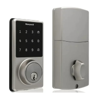
Digital Touchscreen Deadbolt
Model 8733500
Read this manual carefully before installing and operating!
• Phillips Screwdriver
Tools Needed for Lock Installation:
Refer to Template included
for Door Prep Instructions
Example
NOTE: Skip this step if your door comes with pre-drilled holes.
Preparing Door
• Drill
• 2 1/8” Hole Saw
• 1” Hole Saw
• 3/4” Chisel
Tools Needed for Door Preparation
(if there is no knob hole):
2 1/8” Hole Saw
Strike Plate Installation
NOTE: The strike plate on the door frame
needs to be straight and not protruding from
door frame. Make adjustment before installing
or this will cause problems with bolt
fitting into latch hole.
1” Hole Saw
E
Test unlocking
Press 1-2-3-4-unlock
Test the lock button with door open
Before Opening Door
Let Motor Complete Cycle
NOTE: Let lock operation complete before attempting another action
Do not over-tighten latch screws.
A
VERTICAL
POSITION
Check that the Rubber Gasket is secured on the Exterior Assembly. Insert the
Exterior Assembly onto the door with the tailpiece going through the Deadbolt
Latch Set in the VERTICAL POSITION.
Route the Control Wire through the door UNDER the Deadbolt Latch Set. Make
sure the door is shut, lock and unlock using the key, ensure that the latch is
operating smoothly and is aligned properly without scraping the strike plate.
If not, go back to step 2 and ensure you followed the steps.
(K) screw goes into the door to
prevent the lock from shifting and
is optional.
Secure mounting plate to door
L (optional)
I
C
Test the lock
Lock and unlock using the turn knob make sure the latch is opening and
closing easily. If not, go back to step 2 and ensure you followed the steps.
NOTE: Make sure the Turn Knob is in the vertical position.
Be careful not to pinch the control wire when assembling.
J
B
H
C
Please carefully check the above list to confirm all items have been received. If any items are
missing, please contact Consumer Assistance. (See back for contact information)
2 - Keys 1 - 1 3/8” Screw 2 - Mounting Posts
1 - Optional Set Screw
1 - Exterior Faceplate 1 - Strike Plate 2 - 5/16” Screws
1 - Interior Faceplate 1 - Mounting Plate 2 - 1” Screws
1 - User Guide 1 - Latch 4 - 3/4” Screws
Package Includes:
J
3/4” Screws
I
5/16” Screws
D
Keys
Mounting Posts
L M
B
Interior Faceplate
A
Exterior Faceplate
C
Mounting Plate
F
Strike plate
K
Optional Set Screw
H
1” Screws
G
1 3/8” Screw
E
Latch
User Guide
Guide
This Electronic lock requires (4) High Quality AA Alkaline batteries.
When all 4 batteries are installed in the correct position, you should
hear 2 beeps and the touchscreen will illuminate.
The Lock motor will engage and do a series of locking and unlocking
motions in order to automatically determine your door “Handing”
(left or right handed door).
When completed the lock will beep and the touchscreen will flash.
NOTE: Do not touch the touchscreen or turn knob until
the light turns off.
Do not use rechargeable batteries or non-alkaline batteries.
B
TO CONVERT FROM 2-3/8” (60mm) BACKSET TO 2-3/4” (70mm) BACKSET:
1. Hold latch with numbers facing forward and thumb pressing on the bolt.
2. Rotate the cylinder cover clockwise.
3. Pull and twist the extension plate all the way out.
4. Rotate the cylinder counter clockwise so that the marking aligns with
the 2-3/4” position indicator.
The latch plate on the door needs to be straight and not protruding
from door. Make adjustment before installing or this will cause
problems with bolt fitting into latch hole.
2-3/4” position
2-3/8” position
NOTE: Do not extend Cylindrical Cover past 2-3/4” (70mm).
E
Deadbolt Latch Must Be
Retracted During Installation.
Preparation for Interior Assembly.
Screw Mounting Post (M)
into holes on Mounting Plate (C).
M
C
Remove (J) Screw from inside
the battery compartment within the
(B) Housing to release the Mounting
Plate (C).
J
B
C
E
J
Carefully insert control wire
into the wire connector
B
C
NOTE: Make sure the connector dots line up with the dots on the control wire
Important
Use the QR code below for the most up to date instructions:
A
B
L
J
J
C
D
E
F
M
I
K
Do not
overtighten
screws
K
F
Work with the door open
Work with the door open
Turn Knob