Aquastat L4006,7,8;L6006,7,8
5 60-2104—01
Fig. 3 Approximate installation dimensions in inches
(mm) for surface mount models.
Fig. 4 Approximate immersion well dimensions in inches
(mm) for all models except L4006C and L6006B.
Fig. 5 Approximate boiler fitting and bulb dimensions in
inches (mm) for L4006C and L6006B.
1/2 — 14 IN. NPT
7/16
(11)
3 (76)1-1/2 (38)
M8789B
1/2 OR 3/4 — 14 IN. NPT
3/8
(10)
3 (76)
1-5/16 (33)
M8799B
Dimensions:
Installation: (See Figures 1, 2, and 3).
Immersion Well: (See Fig. 4).
Boiler Fitting and Bulb: (See Fig. 5).
DIMENSIONS
Fig. 1 Approximate case installation dimensionsin
inches (mm) for direct insertion models.
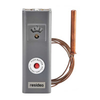
Fig. 2 Approximate installation dimensions in inches
(mm) for remote bulb models. Otherdimensions are the
same as Fig. 1.
M8957A
KNOCKOUT FOR 3/4 (19 )
CONDUIT ON ALL MODELS. SIMILAR
KNOCKOUT ON BOTTOM FOR
HORIZONTAL INSERTION AND
REMOTE BULB MODELS.
1 (25)
5/16
(8)
2 (51)
2-1/8 (54)
5-5/8
(136)
1-7/8
(48)
3/16
(5)
RESET
BUTTON
(L4006E,
L4008E
ONLY)
KNOCKOUT FOR 3/4 (19)
CONDUIT ON VERTICAL
INSERTION MODELS ONLY
ELEMENT FOR HORIZONTAL IMMERSION
3/4
(19)
ELEMENT
FOR VERTICAL
IMMERSION
11/16
(18)
3/4
(19)
SENSING
ELEMENT
CAPILLARY
3/8 (10)
1-1/4
(32)
ALTERNATE POSITION
OF SENSING ELEMENT
CAPILLARY
13/64
(5) (3)
MOUNTING
HOLE FOR
3/16 IN. (5 MM)
SCREW (3)
15/16
(24)
4-3/16
(106)
ALTERNATE POSITION
OF SENSING ELEMENT
CAPILLARY
M8823
M8958B
7/8 IN. (22 MM)
STANDARD
KNOCKOUT (2)
1
(25)
2 (51)
5-5/8
(136)
2-3/4 (70)
2 (51)
C
L
 Loading...