® U.S. Registered Trademark
Copyright © 2001 Honeywell • • All Rights Reserved
INSTALLATION INSTRUCTIONS
69- 1521- 2
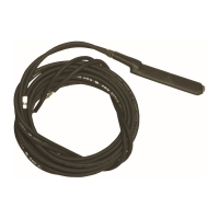
The C7735A1000 Discharge Air Temperature Sensor
(DATS) is a duct-mounted temperature probe that
provides capacity control of heating and cooling
equipment. The DATS is used only with zoning solutions,
including TZ-3, MABS EZ-2 and MABS EZ-4, and EMM-
3 and EMM-3U control panels. Mounted in the supply air
duct, the DATS senses the delivered air temperature and
cuts off the heating or cooling when the delivered air
temperature goes above or below normal operating
limits.
When either limit setting is reached, the appropriate heat
or cool light emitting diode (LED) flashes on the TZ-3 or
EMM series panels, indicating that heating or cooling is
shut off. The call still exists and heated or cooled air is
still being supplied to the calling zones. Once the
delivered air temperature drops ten degrees for heating,
or rises ten degrees for cooling, the heating or cooling
equipment is brought back on. The ten-degree
differential provides adequate minimum time-off to avoid
damaging the equipment. EMM series has a 2.5 minute
timer as equipment protection.
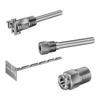
The location of the DATS is critical; it should not be
placed in line-of-sight of the heat exchanger or cooling
coil because the DATS could activate prematurely. It
should also be located before the bypass damper, when
applicable. DATS dimensions are shown in Fig. 1.
The DATS requires only two wires. Normal 18 to 22
gauge thermostat wire is used for shorter runs. For
longer runs or when wiring near voltage, shielded cable
is used.
Fig. 1. C7735A dimensions in in. (mm).
When Installing this Product...
1.
Read these instructions carefully. Failure to follow
them could damage the product or cause a hazard-
ous condition.
2.
Check the ratings given in the instructions and on
the product to make sure the product is suitable for
your application.
3.
Installer must be a trained, experienced service
technician.
4.
After completing installation, use these instructions
to check out the product operation.
IMPORTANT
Do not locate the DATS probe in a duct near the
heat exchanger or strip heat, which can cause
false temperature readings.
1.
Locate the DATS on the supply trunk between the
bypass damper and the evaporator coil and/or heat
exchanger. If a bypass damper is not used, locate
the DATS between the zone dampers and the
evaporator coil and/or heat exchanger. See Fig. 2.
Fig. 2. DATS mounting location.
M14926
4-1/8 (102)
3-7/8
(77)
3-3/4
(77)
1-1/4
(25)
ZONE DAMPERS
BY PASS DAMPER
PLACE SENSOR
INTHIS AREA.
DO NOT
PLACE
SENSOR IN
THIS AREA.
M14877
EVAPORATOR COIL
HEAT EXCHANGER
BLOWER