Do you have a question about the Honeywell Smartronic70 T9275A1002 and is the answer not in the manual?
Details PI control, actuator compatibility, adjustable parameters (ZEB, PID), and sensor options.
Covers 2-Pipe AHU Cooling/Heating, 2-Pipe AHU with Electric Heater, and 4-Pipe AHU systems.
Describes setting point in proportional band and AO proportional to measured temperature.
Explains how DI open triggers reset, power cut-off, and requires manual restart.
Details setpoint in Zero Energy Band, 2-position heating, and modulating cooling control.
Describes DI input for emergencies, leading to output reset and power interruption.
Explains setpoint in Zero Energy Band, 2-position cooling, and modulating heating control.
Details modulating heating, setpoint in proportional band, and alarm on exceeding limit.
Explains DI activation during emergencies, causing output reset and power interruption.
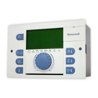
Illustrates the pluggable terminal block design and numbered terminals for connections.
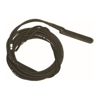
Details power supply inputs, actuator connections, and remote sensor wiring.
| Power Supply | 24VAC |
|---|---|
| Display | LED |
| Output | Relay |
| Input | Thermistor |
| Application | HVAC |