EasyManua.ls Logo

Honeywell MAXON VALUPAK-II 300 User Manual

Honeywell MAXON VALUPAK-II 300
12 pages
To Next Page IconTo Next Page
Page #1 background imageLoading...
Page #1 background image
TECHNICAL CATALOG
32-00188-01
VALUPAK®-II
Low Temperature Burners
High turndown
•Available in 4 sizes
Capacities 2 kW - 558 kW (HHV)
Stable and clean combustion
Suitable for UV scanner and flame rod
Low gas pressure requirements
Ease of installation and operation with low
maintenance requirements
All metal construction
Multi voltage and frequency blower motors
Better control on CO over the entire turndown of the
burner
Pilot connection availability
Easily Switch between Natural Gas and Propane
PRODUCT DESCRIPTION
The VALUPAK®-II is designed for process air heating
applications.
A motorized gas control valve controls the heat output of
the burner over the full operating range. The gas flows
through the nozzle and then along the inside of the burner
cone where combustion air is progressively and
tangentially mixed with the gas. This results in a short, very
stable flame and clean combustion.
Like many other Honeywell products, the standard
VALUPAK-II burner can be customized into a package
which could include a gear motor, burner controls,
automatic shut-off valves, flame sensors and/or pressure
switches.
Question and Answer IconNeed help?

Do you have a question about the Honeywell MAXON VALUPAK-II 300 and is the answer not in the manual?

Honeywell MAXON VALUPAK-II 300 Specifications

General IconGeneral
Ignition TypeDirect Spark Ignition (DSI)
Maximum BTU300, 000 BTU/hr
Fuel TypeNatural Gas
Input Voltage120V AC, 60Hz
Operating Pressure3.5" WC (Natural Gas), 10" WC (Propane)

Summary

Product Description and Features

PRODUCT DESCRIPTION

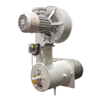
Describes the VALUPAK-II burner for process air heating applications, detailing its motorized gas control valve and combustion process.

Available Burner Sizes and Specifications

AVAILABLE VALUPAK®-II SIZES

Presents selection data for VALUPAK-II burners based on capacity and frequency, detailing various sizes and blower types.

SPECIFICATIONS OF VALUPAK®-II BURNERS FOR 50 HZ OPERATION

Lists detailed technical specifications for VALUPAK-II burners operating at 50 Hz, including heat release, gas flow, and motor data.

Burner Dimensions

DIMENSIONS – VALUPAK®-II 60

Provides detailed dimensional drawings and measurements for the VALUPAK-II 60 model, including various reference points.

DIMENSIONS – VALUPAK®-II 150, 300 & 600

Presents dimensional data and diagrams for VALUPAK-II models 150, 300, and 600, specifying key measurements.

Applications and Options

APPLICATIONS

Highlights specific applications for VALUPAK-II burners, such as textile machines and printing machines, and notes resonance reduction.

Application examples VALUPAK®-II

Illustrates typical use cases for the VALUPAK-II burner within various industrial processes.

Installation and Operating Instructions

INSTALLATION AND OPERATING INSTRUCTIONS

General guidelines and precautions for installing and operating the VALUPAK-II burner system.

Installation of flame scanner

Details on applying a flame scanner to VALUPAK-II burners, excluding the 60 model, without modification.

Operating instructions

Provides basic operating instructions for the VALUPAK-II burner, emphasizing system manufacturer guidelines.

START-UP AND ADJUSTMENT INSTRUCTIONS FOR VALUPAK®-II BURNERS

Instructions for initial start-up and adjustment, requiring trained personnel and adherence to safety protocols.

Flame Rod and Spark Ignitor Arrangement

Flame rod or UV scanner arrangement with spark ignitor

Details the arrangement for flame rod or UV scanner with a spark ignitor for VALUPAK-II burner sizes.

Related product manuals