SERIES 90 MODUTROL IV™ MOTORS
9 63-2190—3
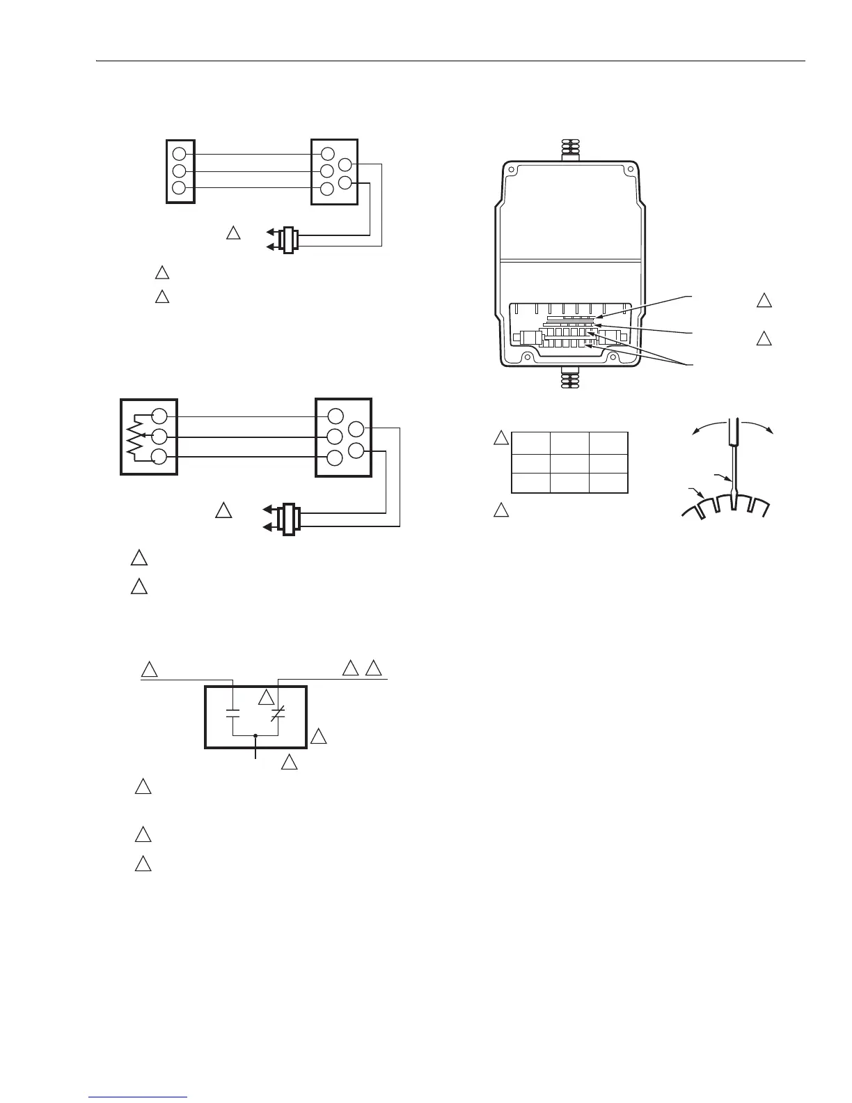
Fig. 6. Typical Series 90 wiring.
Fig. 7. Wiring for potentiometer control.
Fig. 8. Auxiliary switch schematic.
Fig. 9. Stroke adjustment setup for
non-spring return models.
Auxiliary Switches
Adjustable cams actuate the auxiliary switches. These cams
can be set to actuate the switches at any angle within the
stroke of the motor. Select switch differential of 1° or 10°.
Motors with factory-added auxiliary switches are shipped in
the closed position (fully counterclockwise, as viewed from the
power end). Auxiliary cam default actuates the switches 30°
from full open with a 1° differential. With the motor in the
closed (fully counterclockwise) position, the auxiliary switch
breaks contacts R-B. See Fig. 8 (or the auxiliary switch
Instruction Sheet) for auxiliary switch wiring.
NOTE: Auxiliary switches can only be added to motors that
include auxiliary switch cams. (These cams cannot
be field-added.)
TRADELINE motors are shipped with auxiliary switch cams
that permit acceptance of 220736A,B Internal Auxiliary Switch
Kits. Refer to form 63-2228 for 220736A,B installation
instructions.
L1
(HOT)
L2
1
1
2
R
W
B
R
W
B
T1
T2
TRANSFORMER
POWER SUPPLY. PROVIDE DISCONNECT MEANS AND
OVERLOAD PROTECTION AS REQUIRED.
TRANSFORMER MAY BE INTERNAL OR EXTERNAL
M770A
SERIES 90
CONTROLLER
MOTOR
L1
(HOT)
L2
1
1
2
R
W
B
R
W
B
T1
T2
TRANSFORMER
POWER SUPPLY. PROVIDE DISCONNECT MEANS AND
OVERLOAD PROTECTION AS REQUIRED.
TRANSFORMER MAY BE INTERNAL OR EXTERNAL
M18974
m
Potentiometer
MOTOR
BLUE LEAD
YELLOW LEAD
RED LEAD
USE NEC CLASS 1 WIRING UNLESS POWER SUPPLY
MEETS CLASS 2 REQUIREMENTS. TAPE UNUSED LEADS.
ENSURE THE CURRENT DRAW OF THE EXTERNAL CIRCUIT
IS LESS THAN SWITCH CONTACT RATING.
ON TWO-SWITCH MOTORS, SECOND SWITCH HAS BLACK
LEADS WITH BLUE, YELLOW, AND RED TRACERS.
SOME AUXILIARY SWITCH ASSEMBLIES INCLUDE ONLY
RED AND YELLOW LEADS. SOME OTHERS DO NOT INCLUDE
THE YELLOW LEAD.
M17099
1
1
1
2
2
2
2
3
3
OUTER STROKE
ADJUST CAM
OUTER STROKE ADJUST CAM IS ONLY
PRESENT ON HIGH TORQUE MOTORS.
M17100
POWER END
OF MOTOR
INNER STROKE
ADJUST CAM
AUXILIARY
SWITCH CAMS
MOVE SCREWDRIVER AT
TOP ONLY TO ADJUST CAM.
1/8 INCH
STRAIGHT-BLADE
SCREWDRIVER
CAM
1
2
1
2
TORQUE
NO. OF
CAMS
CAM
COLOR
HIGH
LOW
2
1
YELLOW
BROWN
 Loading...