EasyManua.ls Logo

Honeywell Modutrol IV 90 Series User Manual

Honeywell Modutrol IV 90 Series
16 pages
To Next Page IconTo Next Page
Page #1 background imageLoading...
Page #1 background image
PRODUCT DATA
63-2631-07
Series 90
Modutrol IV
Motors
APPLICATION
The Series 90 Modutrol IV
Motors are spring return and
non-spring return modulating proportional control motors. Use
these motors with controllers that provide a Series 90 output
to operate dampers or valves.
FEATURES
Replaces M934A,D, M941, M944A,C,D, M945A,D,F,
M954, M965, and M975 motors.
Integral junction box provides NEMA 3 weather
protection.
Integral spring return returns motor to normal position
when power is interrupted.
Motor and circuitry operate from 24 Vac. Models
available with factory installed transformer, or a field
added internal transformer.
Quick-connect terminals are standard—screw terminal
adapter is available.
Adapter bracket for matching shaft height of older
motors is available.
Motors have field adjustable stroke (90° to 160°).
Die-cast aluminum housing.
Integral auxiliary switches are available factory
mounted, or can be field added.
Nominal timing standard of 30 seconds (90° stroke),
and 60 seconds (160° stroke). Other timings available.
Spring return motors can operate valve linkages form
power end or auxiliary end shafts for normally closed
or normally open valve applications.
All models have dual shafts (slotted and tapped on
both ends).
All models have auxiliary switch cams.
Fixed torque throughout the entire voltage range.
Motors are designed for either normally open or
normally closed valves and dampers.
Field addable interface modules can be mounted in the
junction box to upgrade the motor to Series 70
(electronic) control.
Contents
Application ........................................................................ 1
Features ........................................................................... 1
Specifications ................................................................... 2
Ordering Information ........................................................ 2
Wiring ............................................................................... 7
Settings and Adjustments ................................................. 10
Operation .......................................................................... 11
Checkout .......................................................................... 13
Replacement .................................................................... 13
Question and Answer IconNeed help?

Do you have a question about the Honeywell Modutrol IV 90 Series and is the answer not in the manual?

Honeywell Modutrol IV 90 Series Specifications

General IconGeneral
BrandHoneywell
ModelModutrol IV 90 Series
CategoryEngine
LanguageEnglish

Summary

Application

Features

Specifications

Ambient Temperature Ratings

Specifies the operating temperature range for the motors.

Dead Weight Load On Shaft

Details maximum load capacities for motor shafts.

Ordering Information

Installation

Installation Safety Precautions

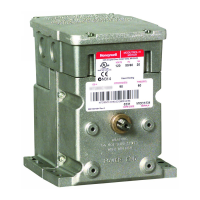
Critical safety warnings and cautions to prevent damage or injury during installation.

Location Considerations

Guidance on selecting a suitable location for motor installation.

Motor Mounting

Guidelines and methods for securely mounting the motor, including bracket use.

Adapter Bracket Use

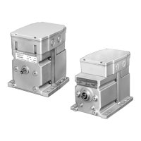
Information on the adapter bracket for shaft height adjustment.

Linkage Considerations

Specifics for damper and valve linkage connections.

Junction Box Functionality

Role of the junction box for protection and wiring.

Wiring

Wiring Safety Precautions

Electrical shock and equipment damage warnings.

Wiring Best Practices

Guidelines for voltage, frequency, parallel connections, and terminals.

Slaving Application Configuration

Details on configuring motors for slaving applications with Series 60 controllers.

Settings and Adjustments

Stroke Setting Procedure

Step-by-step guide for adjusting the motor's operational stroke range.

Adjustable Timing

Information on adjusting the timing for specific motor models.

Auxiliary Switch Adjustment

Procedure for setting auxiliary switch cams for specific actuation points.

Operation

Modutrol IV Motor Operation

Explanation of how the motors function within a control loop.

Checkout

Checkout Procedure

Steps to verify proper motor and linkage function after installation.

Replacement

Damper Application Replacement

Instructions for replacing motors in damper applications.

Valve Application Replacement

Instructions for replacing motors in valve applications.

Related product manuals