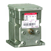
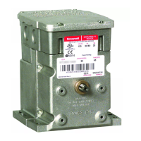
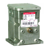
SERIES 90 MODUTROL IV
™
MOTORS
5 63-2631—07
Q181 Auxiliary Potentiometer for sequence or unison control of
1 to 4 additional modulating (Series 90) motors.
Q209E,F Potentiometer limits motor minimum position.
Q5001 Bracket and Linkage Assembly connects Modutrol
Motor to a water or steam globe valve.
Q605 Damper Linkage connects motor to damper. Includes
motor crank arm.
Q607 External Auxiliary Switch controls auxiliary equipment as
a function of motor position.
Q7130A Interface Module with selectable voltage ranges
(4-7 Vdc, 6-9 Vdc, and 10.5-13.5 Vdc) adapts motor to
M71XX function.
Q7230A Interface Module with selectable control (2-10 Vdc or
4-20 mA) and adjustable zero and span adapts motor to
M72XX function.
Q7330A Interface Module for W936 Economizer applications
adapts motor to M73XX function.
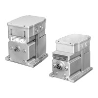
ES650-117 Explosion-Proof Housing encloses motor for use in
explosive atmospheres. Also required, a 7617DM coupling
assembly from Honeywell to use with the cover. Not for use
with Q5001 (or any other valve linkages).
To order ES-650-117, contact EGS Enclosures at
(281) 449-6271, ask for the sales department and for
distribution in your area.
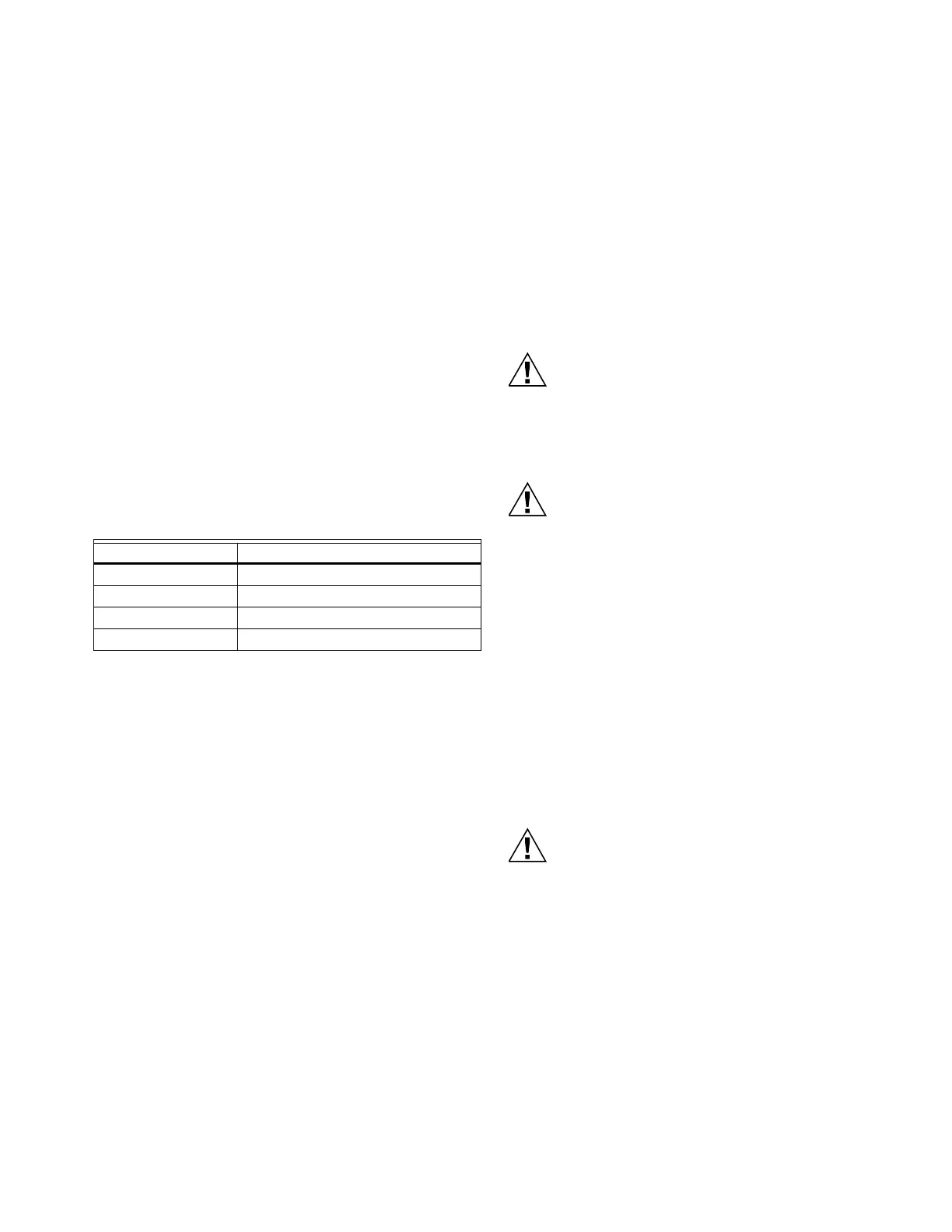
Table 6. Modutrol Motor Cross-Reference.
INSTALLATION
When Installing this Product...
1. Read these instructions carefully. Failure to follow them
could damage the product or cause a hazardous condi-
tion.
2. Check the ratings given in the instructions and on the
product to make sure the product is suitable for your
application.
3. Installer must be a trained, experienced service techni-
cian.
4. After installation is complete, check out product opera-
tion as provided in these instructions.
Electrical Shock or Equipment Damage Hazard.
Can shock individuals or short equipment circuitry.
Disconnect all power supplies before installation.
Motors with auxiliary switches can have more than one
disconnect.
Equipment Damage Hazard.
Can damage the motor beyond repair.
Never turn the motor shaft by hand or with a wrench.
Forcibly turning the motor shaft damages the gear train
and stroke limit contacts.
IMPORTANT
Always conduct a thorough checkout when
installation is complete.
Location
Allow enough clearance for installing accessories and motor
servicing when selecting a location (See Fig. 2). If located
outdoors, use liquid-tight conduit connectors with the junction
box to provide NEMA 3 weather protection. If mounted
outdoors in a position other than upright, install a 4074ERU
Weatherproofing Kit and liquid-tight connectors to provide
NEMA 3 protection.
Motor Damage Hazard.
Deteriorating vapors and acid fumes can damage
metal parts.
Install motor in areas free of acid fumes and other
deteriorating vapors.
In excessive salt environments, mounting base and screws
should be zinc or cadmium plated, not stainless steel or brass.
Use the 220738A Adapter Bracket for mounting on these
surfaces.
Original Motor Replacements
M944A,C,D, M954 M9184, M9194
M934D M9164, M9174
M945A,D,F, M955 M9182, M9185
M941 M9484, M9494
 Loading...