PRODUCT DATA
63-2629—2
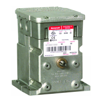
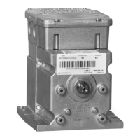
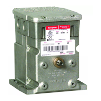
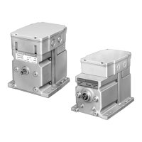
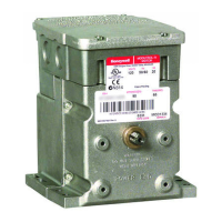
Series 61 and Series 62
Modutrol IV™ Motors
APPLICATION
The Series 61 and Series 62 Modutrol IV™ Motors are
three-wire spring return and non-spring return floating control
motors. Use these motors with controllers that provide a
switched spdt or floating output to operate dampers or valves.
The Series 62 motors have an internal electrically isolated
feedback potentiometer that provides indication of the motor
shaft position and can be used for slaving Series 90 Motors or
rebalancing an external control circuit.
FEATURES
• Replaces M644, M944B,E,G,H,J,K,R,S and
M945B,C,G,K,L,AD Motors.
• Integral junction box provides NEMA 3 weather
protection.
• Integral spring return returns motor to normal position
when power is interrupted.
• Motor and circuitry operate from 24 Vac. Models
available with factory installed transformer, or a field
added internal transformer.
• Quick-connect terminals are standard—screw terminal
adapter is available.
• Adapter bracket for matching shaft height of older
motors is available.
• Motors have field adjustable stroke (90° to 160°).
• Die-cast aluminum housing.
• Integral auxiliary switches are available factory
mounted, or can be field added.
• Nominal timing standard of 30 seconds (90° stroke),
and 60 seconds (160° stroke). Other timings available.
• Spring return motors can operate valve linkages from
power end or auxiliary end shafts for normally closed
or normally open valve applications.
• All models have dual shafts (slotted and tapped on
both ends).
• All models have auxiliary switch cams.
• Fixed torque throughout the entire voltage range.
• Motors are designed for either normally open or
normally closed valves and dampers.
• Series 62 models include electrically isolated feedback
potentiometer that provides shaft position indication.
• Series 62 TRADELINE models have linear feedback,
configurable for slaving Series 90 Motors.
Contents
Application ........................................................................ 1
Features ........................................................................... 1
Specifications ................................................................... 2
Ordering Information ........................................................ 2
Installation ........................................................................ 4
Settings and Adjustments ................................................. 7
Operation .......................................................................... 10
Checkout .......................................................................... 10
Replacement .................................................................... 10