SERIES 61 AND SERIES 62 MODUTROL IV™ MOTORS
63-2629—2 6
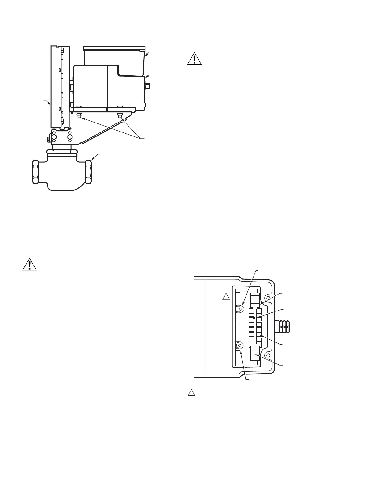
Fig. 4. Mounting the motor on a Q5001 Valve Linkage.
Damper Linkages
The motor does not include a crank arm. Order the crank arm
separately (see Accessories in the Specifications section). For
detailed instructions on the assembly of specific linkages, refer
to the Installation Instructions packed with the linkage.
Equipment Damage Hazard. Stalling a motor can
damage the drive shaft.
Ensure installation of motors and linkages allows the
motor to drive through full stroke without obstruction.
Valve Linkages
The Q100 Linkage requires a 220738A Adapter Bracket for all
valve applications. Applications with the Q5001 Valve Linkage
do not require the 220738A Adapter Bracket (see Fig. 4).
Junction Box
When used with liquid-tight conduit connectors, the junction
box provides NEMA 3 weather protection for the motor. The
junction box, standard with replacement motors, encloses the
terminals and provides knockouts for wiring conduits. Housing
an internal transformer or internal auxiliary switches requires
using a junction box.
Wiring
Electrical Shock or Equipment Damage Hazard.
Can shock individuals or short equipment circuitry.
Disconnect all power supplies before installation.
Motors with auxiliary switches can have more than one
disconnect.
IMPORTANT
All wiring must agree with applicable codes,
ordinances and regulations.
1. Ensure that the voltage and frequency stamped on the
motor correspond with the power supply characteristics.
2. When connecting several motors in parallel, ensure that
the power supply VA rating is large enough to provide
power to all motors used without overloading.
3. Fig. 5 shows that motor terminals are quick-connects
located on top of the printed circuit board.
4. To access the wiring compartment:
a. Remove the four screws from the junction box top.
b. Lift off the cover.
5. Refer to Fig. 6 for typical wiring, and Fig. 9 for internal
auxiliary switch connections.
NOTE: Reverse motor rotation by switching wires at either
the motor or panel. Reverse rotation on Series 61
models by reversing wires at terminals W and B.
Reverse rotation on Series 62 models by reversing
wires at terminals 1 and 2 (to correct motor rotation)
and reverse wires at terminals Y and G (to maintain a
feedback signal that corresponds with shaft rotation),
Fig. 5. Terminals and adjustments.
1/4-20 UNC
1 in. LONG
MOUNTING
BOLTS
Q5001
VALVE
LINKAGE
M18994
MOTOR
JUNCTION
BOX
POWER
END OF
MOTOR
VALVE
INNER AUXILIARY
SWITCH
INNER AUXILIARY
SWITCH CAM (BLUE)
POWER
END
OUTER AUXILIARY
SWITCH CAM (RED)
OUTER AUXILIARY
SWITCH
ADJUSTABLE STROKE
POTENTIOMETER
SERIES 62 TERMINAL DESIGNATIONS SHOWN.
NOTE: NOT ALL FEATURES AVAILABLE ON ALL MODELS.
M13600B
Y
T
G
R
4
2
1
3
1
1
SENSITIVITY POTENTIOMETER
(ON SOME SERIES 62 MODELS, SEE TABLE 5)
 Loading...