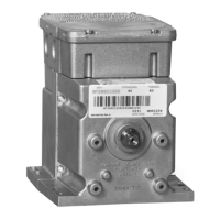
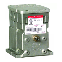
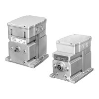
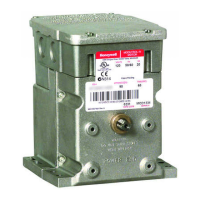
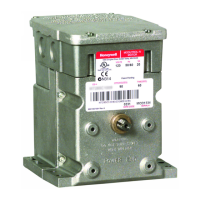
SERIES 61 AND SERIES 62 MODUTROL IV™ MOTORS
63-2629—2 2
ORDERING INFORMATION
When purchasing replacement and modernization products from your TRADELINE® wholesaler or distributor, refer to the
TRADELINE® Catalog or price sheets for complete ordering number.
If you have additional questions, need further information, or would like to comment on our products or services, please write or
phone:
1. Your local Honeywell Automation and Control Products Sales Office (check white pages of your phone directory).
2. Honeywell Customer Care
1885 Douglas Drive North
Minneapolis, Minnesota 55422-4386
In Canada—Honeywell Limited/Honeywell Limitée, 35 Dynamic Drive, Scarborough, Ontario M1V 4Z9.
International Sales and Service Offices in all principal cities of the world. Manufacturing in Australia, Canada, Finland, France,
Germany, Japan, Mexico, Netherlands, Spain, Taiwan, United Kingdom, U.S.A.
SPECIFICATIONS
Models: TRADELINE models are selected and packaged to
provide ease of stocking, ease of handling and maximum
replacement value. TRADELINE model specifications are the
same as those of standard models unless specified otherwise.
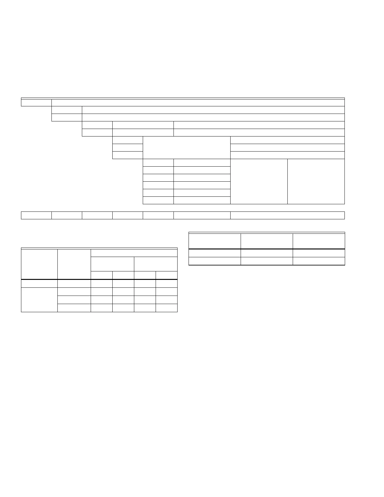
Modutrol IV Order Number Guide: See Table 1.
Dimensions: See Fig. 1.
Table 1. Modutrol IV Series 2 Version Order Number Guide.
Electrical Ratings: See Table 2.
Table 2. Series 61 and 62 Modutrol IV Motor
Power Consumption Ratings.
Auxiliary Switch Ratings: See Table 3.
Control Inputs:
Floating three-wire (Series 60): drive open, hold, drive closed.
Series 62 models include an internal, electrically isolated feed-
back potentiometer that provides shaft position
indication.
Table 3. Auxiliary Switch Ratings.
Ambient Temperature Ratings:
Maximum: 150°F (66°C) at 25% duty cycle.
Minimum: -40°F (-40°C).
Dead Weight Load On Shaft:
Power or Auxiliary End: 200 lb (90.8 kg) maximum.
Maximum Combined Load: 300 lb (136 kg).
Crankshaft: 3/8 in. (9.5 mm) square.
Stroke: Adjustable Stroke Models: Available field-adjustable
from 90° to 160°. (See Stroke Setting procedure.)
Timing And Torque: See Table 4.
M Motor
61 Floating Control
62 Floating Control with feedback
8 60 lb-in. Spring Return 150 lb-in. Non-Spring Return
9 — 300 lb-in. Non-Spring Return
2 Dual-ended shaft Normally Closed Spring Return
4 Non-Spring Return
5 Normally Closed Spring Return
A 0 Auxiliary Switches Adjustable Stroke
Normally Closed
B 1 Auxiliary Switch
C 2 Auxiliary Switches
D 0 Auxiliary Switch
E 1 Auxiliary Switch
F 2 Auxiliary Switches
M 61 8 4 A XXXX See Catalog for Complete O.S. Number
Internal
Transformer
Voltage at
50/60 Hz
Power Consumption
Non-Spring
Return Spring Return
(VA) (W) (VA) (W)
No 24 13 6 19 9
Yes 24 13 6 19 9
120 13 6 19 9
230 13 6 19 9
Single Contact
Rating
a
120V (in Amps) 240V (in Amps)
Full Load 7.2 3.6
Locked Rotor 43.2 21.6
a
40 VA pilot duty, 120/240 Vac on opposite contact.
 Loading...