SET OPERATING RANGE
MP953A,
B
1,
2.
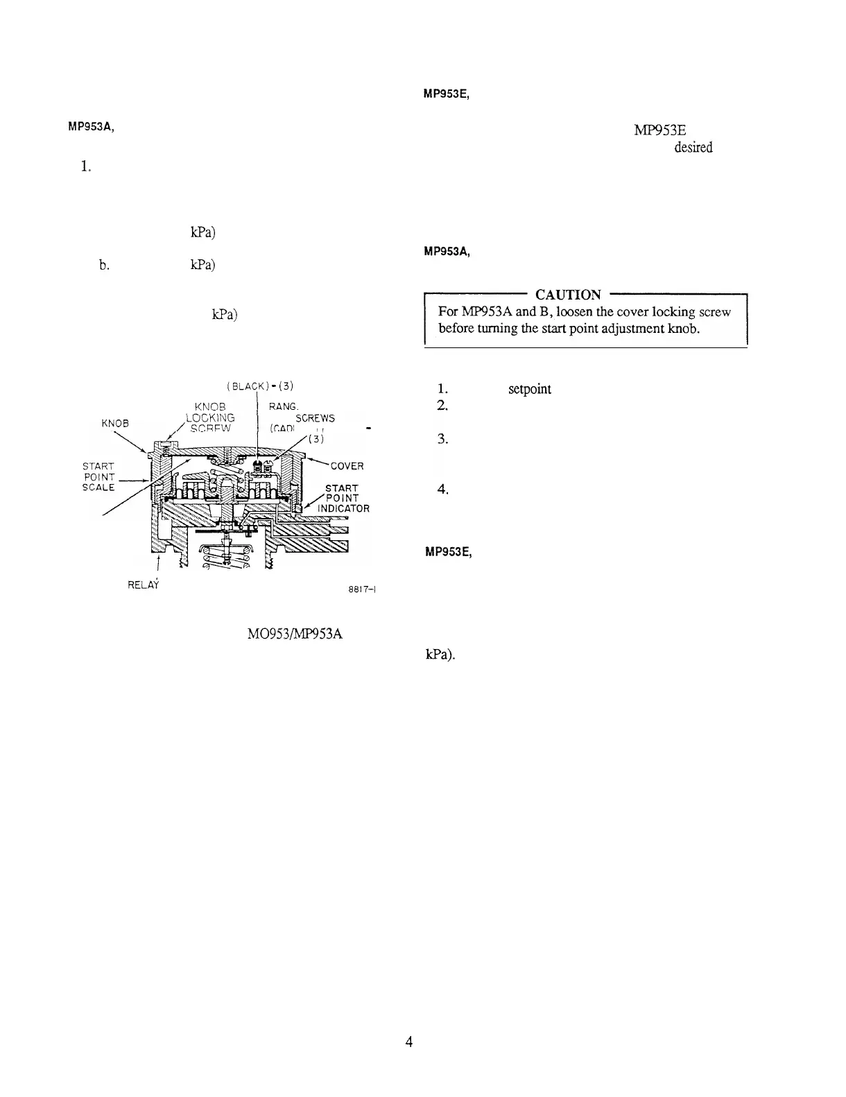
Use Wrench 301572A to loosen the cover locking
screw (Fig. 2).
Unscrew the start point adjustment knob until thread
is disengaged. Remove knob.
a.
For
3
psi (21
kPa)
range, back all range adjustment
screws off to friction stop.
b.
For 5 psi (34
kPa)
range, back only the black range
adjustment screws to stop and tighten the outer,
cadmium-plated range adjustment screws.
c. For 10 psi (69
kPa)
range, tighten all range
adjustment screws.
MP953E,
F
Change the operating range of
MP953E
and F by
replacing the feedback spring with one for the
desired
range
(see REPAIR).
ADJUST START POINT
MP953A, B
RANGE ADJUSTMENT SCREWS
(BLANK)
-
(3)
START POINT
ADJUSTMENT
E ADJUSTMENT
M IUM
PLATED)
-
RANGE
ADJUSTMENT
INSTRUCTIONS
SHOWN HERE
RELA‘i BODY
8817-I
Fig. 2. Adjustment Points of
M0953/MP953A
and B
Gradutrol Relay.
Reinstall
setpoint
knob.
Tighten knob by turning it until it is seated on relay
body (Fig.
2).
Loosen knob (maximum of one turn) until start point
of correct scale range lines up with start point
indicator.
Tighten knob locking screw until it engages relay
body. Do not overtighten.
MP953E, F
Set the start point on the positioner to the value shown on
the job drawings. Critical applications and feedback spring
changes mightrequire fine-tuning the
start point. Each click
of the start point knob will adjust the start
point
0.25 psi (1.7
kPa).
75-5500
4
 Loading...