Do you have a question about the Honeywell ML200R and is the answer not in the manual?
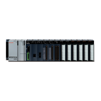
Lists and describes the different CPU types available for the ML200 PLC system.
Details the voltage types supported by the ML200-IEC and ML200R systems.
Categorizes and lists the various modules supported by the ML200 IEC and ML200R.
Describes the main and expansion bases for ML200-IEC and ML200R systems.
Explains the types of cables used for ML200-IEC and ML200R expansion connections.
Lists the power specifications and current consumption for all modules within the PLC.
Guides on choosing the appropriate power module based on system requirements and calculations.
Outlines the requirements for setting up the engineering station for SoftMaster installation.
Specifies the hardware and software needed for installing SoftMaster.
Details essential devices and environmental conditions for PLC system installation.
Provides guidelines for proper grounding of the PLC system in a cabinet.
Lists essential safety and handling precautions for PLC modules.
Explains the process of mounting chassis and inserting modules into the PLC system.
Illustrates the system configuration and architecture for ML200-IEC and ML200R.
Provides instructions and checks required before powering on and starting the PLC system.
Introduces potential errors, their causes, detection, and corrective measures for the system.
Outlines steps and cautions for effectively troubleshooting system faults.
Presents common faults and recommended solutions for input and output circuits.
| Supply Voltage | 24 VDC |
|---|---|
| Series | ML200 |
| Input Voltage | 24 VDC |
| Digital Inputs | 8 |
| Analog Outputs | 2 |
| Enclosure Rating | IP20 |
| Controller Type | PLC |
| Product Type | Programmable Logic Controller |
| Communication Ports | RS-485 |
| Operating Temperature | 0°C to 50°C |
| Humidity | 5% to 95% non-condensing |
