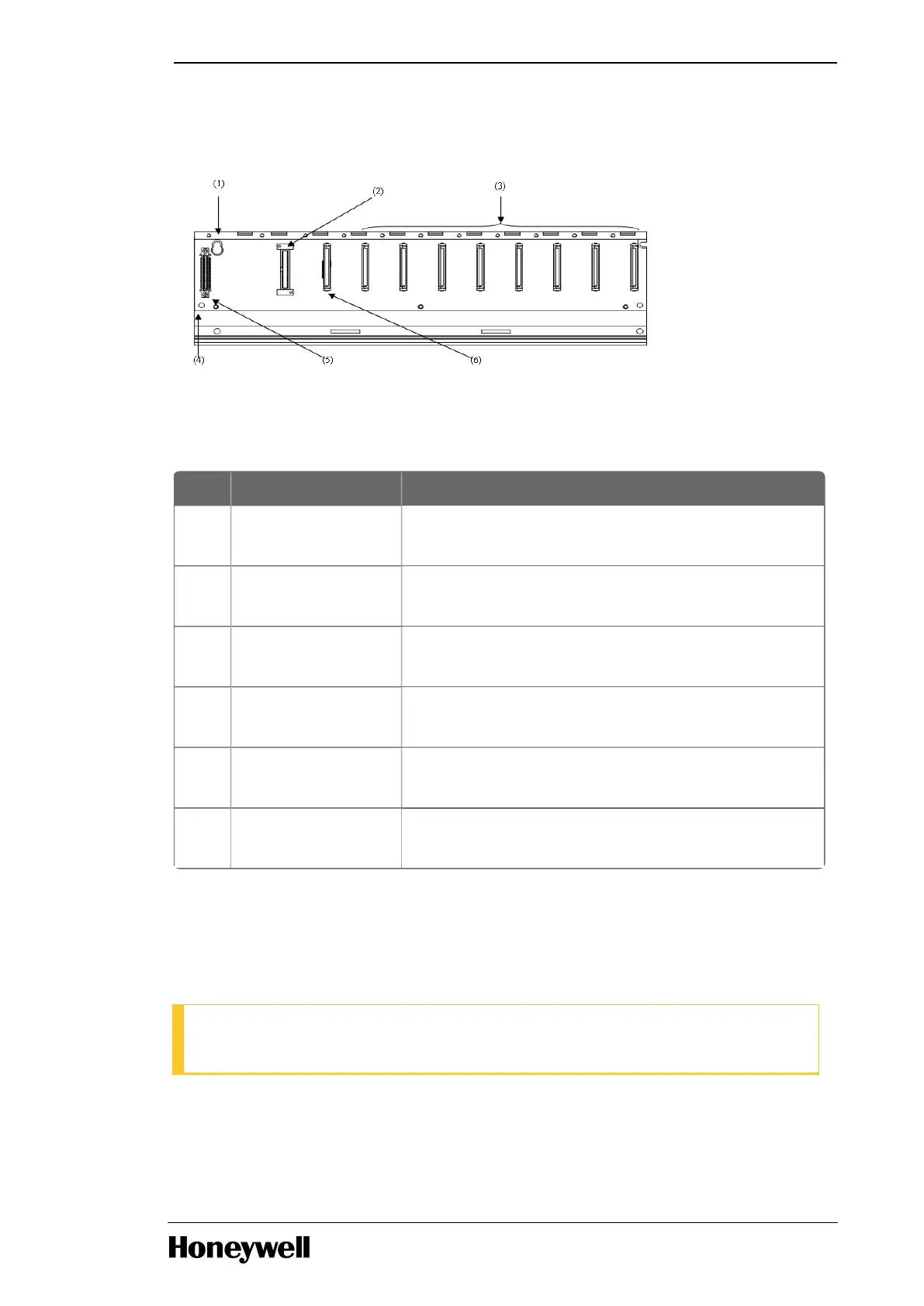
The following image illustrates the main base of ML200-IEC.
Figure 1: Main base of ML200-IEC
The following table lists the details of the main base.
Table 10: Details of main base
Index Part Function
1 Base attached guide
hole
For attaching the main base to the panel in the control
panel.
2 Power module
connector
For installation of Power supply module.
3 Module built-in
connector
For installation of I/O, special and other communication
modules.
4 FG terminal The ground terminal connected to the shielded pattern
of the PCB board.
5 Expansion cable
connector
Connects the main base (CPU base) with the
expansion base.
6 CPU module
connector
For installation of the CPU module.
ML200-IEC Expansion base
The expansion base consists of the power module, I/O module, special module, and the communication
module.
ATTENTION
2MLI CPUS/P does not support the Expansion base.
The following table lists the types of expansion bases for ML200-IEC.
Table 11: Types of expansion bases for ML200-IEC
- 9 -
Chapter 1 - Masterlogic components
 Loading...


