Chapter 3 - Plan and Install MLPLC
l Ensure that the modules are mounted correctly in both the CPU base and the I/O base.
l Ensure the following:
l Synchronization cable is connected between Master and Standby CPUs.
l Expansion cable is connected between I/O racks and CPUs in a Ring Configuration.
l Ensure that both the CPUs are set to different CPU sides. If not, perform the following to set the
CPU sides.
l To set the CPU to side A, move the switch to left and release.
l To set the CPU to side B, move the switch to right and release.
ATTENTION
DO NOT change Boot/Normal switch settings.
l Ensure that the STATION NUMBER is set using the Rotary switch on the Expansion driver
module.
I/O device wiring
Perform the following steps for I/O device wiring.
l The cable used for I/O wiring must be 0.3~2.0mm
2
.
1. Use a separate input and output cable for wiring.
2. Separate the I/O signal cable by a distance of at least 100mm from the main circuit cable of
high voltage/high current.
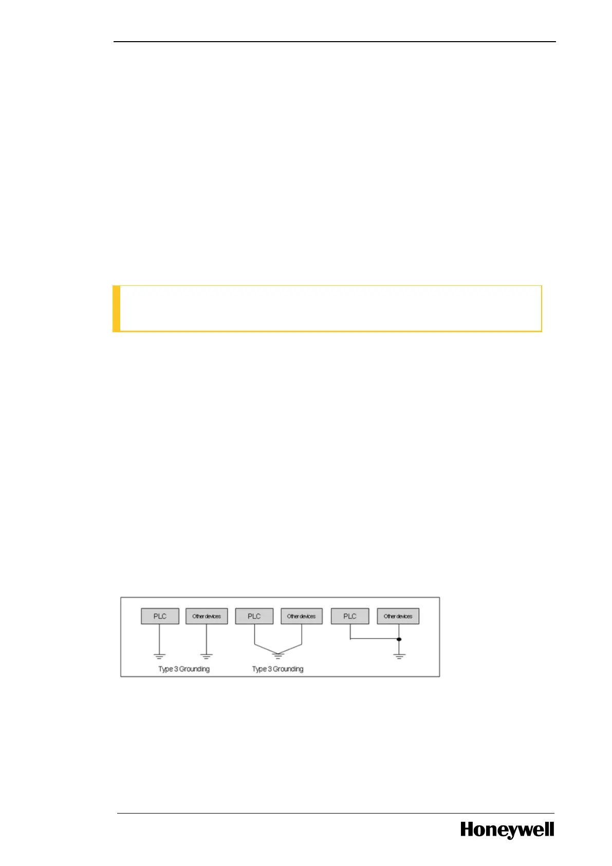
3. If it is not possible to separate the main circuit cable and power cable, use the shielded cable
in all cases and ground the PLC.
4. In case of pipe wiring, check the pipe for grounding properly.
5. Separate output cable of DC 24V from AC 110V cable or AC 220V cable.
- 43 -
 Loading...


