EasyManua.ls Logo

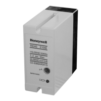
Honeywell RM7850A1019 User Manual

Honeywell RM7850A1019
20 pages
To Next Page IconTo Next Page
Page #1 background imageLoading...
Page #1 background image
INSTALLATION INSTRUCTIONS
32-00198-01
SIL
3
Capable
0063
EC7830A, RM7830A,
EC7850A, RM7850A
7800 SERIES Relay Modules
APPLICATION
The Honeywell EC/RM7830A and EC/RM7850A are
microprocessor-based integrated burner controls for
automatically fired gas, oil, or combination fuel single
burner full modulation (EC/RM7850A) or on/off
(EC/RM7830A) applications. The EC/RM7830A;
EC/RM7850A system consists of a relay module, subbase,
amplifier, and purge card. Options include keyboard
display module (KDM), Data ControlBus™ Module and
remote display mounting.
Functions provided by the EC/RM7830A and
EC/RM7850A include automatic burner sequencing,
flame supervision, system status indication, system or
self-diagnostics and troubleshooting. Text readout on the
Keyboard Display Module is available in various
languages.
This document covers the following 7800 Series Relay
Modules:
EC7830A1033
EC7830A1066
EC7850A1072
EC7850A1080
EC7850A1122
RM7830A1003
RM7830A1029
RM7850A1001
RM7850A1019
EC7830A2033
EC7830A2066
EC7850A2072
EC7850A2080
EC7850A2122
RM7830A2003
RM7830A2029
RM7850A2001
RM7850A2019
This document provides installation and static checkout
instructions. Other applicable publications are:
Form
Number Description
32-00110 S7800A2142 4-line LCD Keyboard Display
Module Product Data
32-00166 204729A/C KDM NEMA4 Covers for 4-line
LCD KDM
32-00235 R7824, R7847, R7848, R7849, R7861,
R7886 Flame Amplifiers for the 7800
SERIES Product Data
65-0084 Q7800A,B 22-Terminal Wiring Subbase
Product Data
65-0090 S7800A Keyboard Display Module Product
Data
65-0091 S7810A Data ControlBus™ Module
Product Data
65-0095 S7820 Remote Reset Module Product
Data
65-0097 221729C Dust Cover Packing Instructions
65-0131 221818A Extension Cable Assembly
Product Data
65-0228 S7810B Multi-Drop Switch Module
Product Data
65-0229 7800 SERIES Relay Modules Checkout
and Troubleshooting Product Data
65-0249 S7810M ModBus Module (For CE ,
Modbus module S7810M1029 only).
65-0295 50023821-001/2 KDM NEMA4 Covers for
classic 2-line VFD KDM
Question and Answer IconNeed help?

Do you have a question about the Honeywell RM7850A1019 and is the answer not in the manual?

Honeywell RM7850A1019 Specifications

General IconGeneral
Current Rating10 A
Contact ConfigurationSPDT
ApplicationGeneral Purpose
Frequency50/60 Hz
Contact FormSPDT
Terminal TypeScrew
ModelRM7850A1019
ApprovalsUL, CSA, CE
Coil Voltage120 VAC
Operating Temperature-40°C to +85°C

Summary

Installation Instructions Introduction

Product Specifications

General Installation Guidelines

Pre-Installation Precautions

Provides critical warnings and general instructions before installation begins.

Safety Warnings

Warns about severe injury, death, or damage from fire, explosion, and electrical shock.

Important Wiring Points

Lists crucial points for correct wiring and system integration.

Wiring Subbase Mounting

Subbase Wiring Procedures

General Wiring Precautions and Guidelines

Covers electrical safety, code compliance, wire routing, and grounding practices.

Final Wiring Checks

Relay Module Mounting on Subbase

Static Checkout Procedures

Checkout Purpose and Reference

Explains the purpose of static checkout and refers to other documents.

General Static Checkout Instructions

Step-by-step guide and precautions for performing the checkout procedure.

Safety Warnings During Static Checkout

Hazard Warnings

Critical warnings about fire, explosion, electrical shock, and equipment damage.

Static Checkout Step-by-Step

Checkout Instructions and Precautions

Detailed steps and recommendations for performing the static checkout.

Key Technical Features

Relay Module Functionality

Highlights core functionalities and advancements of the relay modules.

Safety Shutdown (Lockout) Triggers

Lockout During Initiate Period

Lists conditions causing lockout during the INITIATE period.

Lockout During Standby Period

Lists conditions causing lockout during the STANDBY period.

Lockout During Purge Period

Lists conditions causing lockout during the PURGE period.

Product Operation Overview

Operation Sequences Explained

Ignition Trial Stages

Details preignition, first safety time, and pilot stabilization stages.

Settings and Adjustments

Safety and Security Measures

Related product manuals