21 65-0086—2
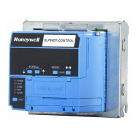
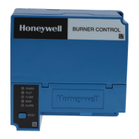
RM7895A,B,C,D
OPERATION
GENERAL INSTRUCTIONS
1. Perform all applicable tests listed in Static Checkout,
Table 5, in the order listed.
2. MAKE SURE THAT ALL MANUAL FUEL SHUT-
OFF VALVE(S) ARE CLOSED.
3. Perform only those tests designated for the specific
RM7895 model being tested.
4. Raise the set point of the operating controller to simu-
late a call for heat.
5. For each test, open the master switch and install the
jumper wire(s) between the subbase wiring terminals listed in
the Test Jumpers column of Table 4.
6. Close the master switch before observing operation.
7. Read the voltage between the subbase wiring terminals
listed in the Voltmeter column of Table 4.
8. If there is no voltage or the operation is abnormal,
check the circuits and external devices as described in the
last column.
9. Check all wiring for correct connections, tight termi-
nal screws, correct wire, and proper wiring techniques.
Replace all damaged or incorrectly sized wires.
10. Replace faulty controllers, limits, interlocks, actuators,
valves, transformers, motors and other devices as required.
11. Obtain normal operation for each required test be-
fore continuing the checkout.
12. After completing each test, be sure to remove the test
jumper(s).
TABLE 4—STATIC CHECKOUT.
Test RM7895 Test Volt- If Operation Is Abnormal,
No. Models Jumpers meter Normal Operation Check The Items Listed Below
WARNING
Make sure all manual fuel shutoff valves are closed.
IMPORTANT: Low fuel pressure limits, if used, could be open. Bypass them with jumpers for the remaining Static Tests
(if required).
1 All None 5-L2 Line voltage at terminal 5. 1. Master switch.
2. Power connected to the master switch.
3. Overload protection (fuse, circuit
breaker) has not opened the power line.
2 All None 6-L2 Line voltage at terminal 6. 1. Limits.
2. Burner controller.
3 All 4-5 7-L2 1. Burner motor (fan or blower) 1. Burner motor circuit.
starts. a. Manual switch of burner motor.
2. Line voltage at terminal 7 b. Burner motor power supply,
within 10 seconds. overload protection and starter.
c. Burner motor.
4 All 5-10 — Ignition spark (if ignition 1. Watch for spark or listen for buzz.
transformer is connected to a. Ignition electrodes are clean.
terminal 10). b. Ignition transformer is okay.
5 All 5-8 — 1. Ignition spark (if ignition 1. Watch for spark or listen for buzz.
transformer is connected to a. Ignition electrodes are clean.
terminal 8). b. Ignition transformer is okay.
2. Automatic pilot valve opens 2. Listen for click or feel head of valve
(if connected to terminal 8). for activation.
NOTE: Refer to wiring diagram a. Actuator if used.
of system being tested. b. Pilot valve.
6 All 5-9 — Automatic fuel valve(s) opens. Same as test no. 6. If using direct spark
If using direct spark ignition, ignition, check the first stage fuel
checkthe first stage fuel valve(s) valve(s) instead of the pilot valve.
instead of the pilot valve.
7 RM7895 5-21 — Automatic delayed main fuel 1. Listen for and observe operation of
C,D valve(s) opens. the delayed main fuel valve(s) and
actuator(s).
2. Valve(s) and actuator(s).
8 All 5 -3 — Alarm (if used) turns on. 1. Alarm
Final All CAUTION
After completing these tests, open the master switch and remove all test jumpers from the
subbase terminals. Also remove bypass jumpers from the low fuel pressure limits (if used).
!
!
 Loading...