INSTALLATION INSTRUCTIONS
66-1094-08
RM7838C1020 only
RM7838B,C
7800 SERIES Relay Module
APPLICATION
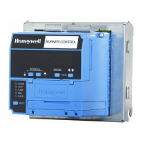
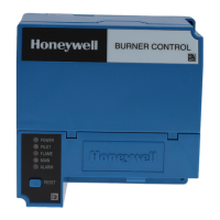
The Honeywell RM7838B,C is a microprocessor based
integrated burner control for industrial process modulating
semiautomatically fired gas, oil, coal or combination fuel
single burner applications. The RM7838B,C System consists
of a relay module, wiring subbase, keyboard display module
(KDM), amplifier, and purge card. Options include Data
ControlBus Module™, remote display mounting, and first-out
expanded annunciator.
Functions provided by the RM7838B,C include automatic
modulated High Fire and Low Fire proven Purge, burner pilot
startup with pilot valve hold, a special pilot valve hold from the
Run condition, flame supervision, system status indication,
system or self-diagnostics and troubleshooting.
The RM7838C differs from the RM7838B as follows:
1. Alarms only on Safety Shutdown.
2. Requires ST7800C Purge Timer.
3. C1004 has 15 second MFEP. C1020 has 5 second
MFEP.
This document provides installation and static checkout
instructions. Other applicable publications are:
65-0084: Q7800A,B 22-Terminal Wiring Subbase
Product Data.
65-0089: ST7800A,C Plug-In Purge Timer
Installation Instructions.
65-0090: S7800A Keyboard Display Module
Product Data.
65-0101: S7830 Expanded Annunciator Product
Data.
65-0109: R7824, R7847, R7848, R7849, R7851,
R7852, R7861, R7886 Flame Amplifiers
for the 7800 Series Product Data.
65-0131: 221818A Extension Cable Assembly
Product Data.
65-0229: 7800 Series Relay Modules Checkout and
Troubleshooting Product Data.
65-0249: S7810M ModBus™ Module Product Data.
SPECIFICATIONS
Electrical Ratings (See Table 4):
Voltage and Frequency: 120 Vac (+10/-15%),
50/60 Hz (±10%).
Power Dissipation:
RM7838B,C: 10W maximum.
Maximum Total Connected Load: 2000 VA.
Fusing Total Connected Load: 15A maximum, type SC or
equivalent, fast blow.
Environmental Ratings:
Ambient Temperature:
Operating: -40°F to +140°F (-40°C to +60°C).
Storage: -40°F to +150°F (-40°C to +66°C).
Humidity: 85% relative humidity continuous, noncondensing.
Vibration: 0.5G environment.
SIL 3 Capable:
SIL 3 Capable in a properly designed Safety Instrumented
System. See form number 65-0312 for Certificate Agree-
ment.
Approvals:
Underwriters Laboratories Inc. Listed: File No. MP268, Guide
No. MCCZ.
Canadian Standards Association Certified: LR9S329-3.
Factory Mutual Approved: Report No. 1V9A0.AF.
Swiss Re (formerly Industrial Risk Insurers): Acceptable.
Federal Communications Commission: Part 15, Class B,
Emissions.
Gastec: EN298, Report 115679/4 (RM7838C1020 only)
IMPORTANT
A Flame Detection System is required for operation
and must be ordered separately. Select the
applicable Flame Signal Amplifier and matching
Flame Detector in form 65-0109.
INSTALLATION
When Installing this Product...
1. Read these instructions carefully. Failure to follow
them could damage the product or cause a hazardous
condition.
2. Check the ratings given in the instructions and marked
on the product to make sure the product is suitable for
the application.
3. Installer must be a trained, experienced, flame
safeguard service technician.
4. After installation is complete, check out the product
operation as provided in these instructions.