1 65-0086—2
B. M. • Rev. 9-93 • ©Honeywell Inc. 1993 • Form Number 65-0086—2
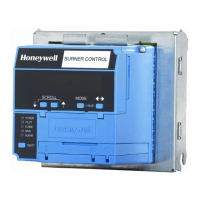
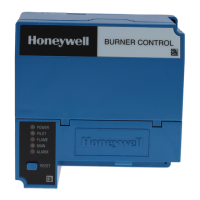
The Honeywell RM7895 is a microprocessor based
integrated burner control for automatically fired gas, oil,
or combination fuel single burner applications. The
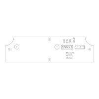
RM7895 consists of the Relay Module. Subbase, Amplifier
and Purge Card are required to complete the system.
Options include Keyboard Display Module, Personal
Computer Interface, DATA CONTROLBUS MOD-
ULE™, Remote Display Module, First-Out Expanded
Annunciator and COMBUSTION SYSTEM MANAGER™
Software.
The RM7895 is programmed to provide a level of
safety, functional capability and features beyond the ca-
pacity of conventional controls.
Functions provided by the RM7895 include automatic
burner sequencing, flame supervision, system status indi-
cation, system or self-diagnostics and troubleshooting.
■ Safety features:
— Airflow switch check.
— Closed loop logic test.
— Dynamic AMPLI-CHECK™.
— Dynamic input check.
— Dynamic safety relay test.
— Dynamic self-check logic.
— Internal hardware status monitoring.
— Tamper resistant timing and logic.
■ Access for external electrical voltage checks.
■ Airflow switch check feature (RM7895B,D).
■ Application flexibility.
■ Communication interface capability.
■ Delayed main valve (RM7895C,D).
■ Dependable, long-term operation provided by microcom-
puter technology.
■ Early spark termination (RM7895A1048 and RM7895C1020).
■ First-out annunciation and system diagnostics provided by
a 2 row by 20 column Vacuum Fluorescent Display (VFD)
located on the optional Keyboard Display Module (optional).
■ First-out expanded annunciation with 26 Light Emitting
Diodes (LEDs) for limits and interlocks (optional).
■ Five (LEDs) for sequence information.
■ Two function Run/Test Switch (RM7895C,D).
■ Interchangeable plug-in flame amplifiers.
■ Local or remote annunciation of RM7895 operation and
fault information.
■ Nonvolatile memory; RM7895 retains history files and
sequencing status after loss of power.
■ Remote reset (optional).
■ Report generation (optional).
■ Selectable recycle or lockout on loss of airflow.
■ Selectable recycle or lockout on loss of flame.
■ Shutter drive output.
■ Burner controller data (optional):
— Expanded annunciator status.
— Flame signal strength.
— Hold status.
— Lockout/alarm status.
— Sequence status.
— Sequence time.
— Total cycles of operation.
— Total hours of operation.
— Fault history providing for the six most recent faults:
• Cycles of operation at the time of the fault.
• Expanded annunciator data at the time of the fault.
• Fault message and code.
• Hours of operation at the time of the fault.
• Sequence status at the time of the fault.
• Sequence time at the time of the fault.
— Diagnostic information:
• Device type.
• Flame amplifier type.
• Flame failure response time.
• Manufacturing code.
• On/Off status of all digital inputs and outputs.
• Selected prepurge time.
• Software revision and version of RM7895 and op-
tional Keyboard Display Module.
• Status of configuration jumpers.
• Status of Run/Test Switch (RM7895C,D).
CONTENTS
Specifications ................................................2
Ordering Information .................................... 2
Principal Technical Features........................ 8
Safety Provisions ........................................... 9
Installation .................................................. 10
Wiring.......................................................... 12
Assembly...................................................... 15
Operation .................................................... 18
Checkout...................................................... 22
Troubleshooting .......................................... 28
7800 SERIES RM7895A,B,C,D
Relay Module