23 65-0086—2
Measure the flame signal at the appropriate times de-
fined in the following checkout tests. Read the flame signal
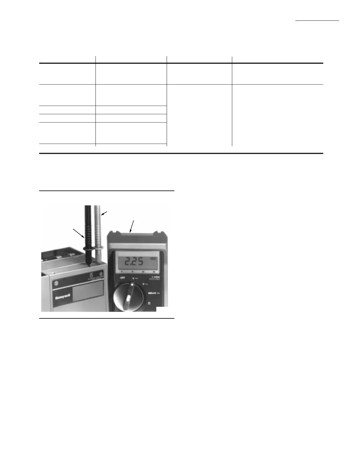
volts dc at the flame amplifier test jacks + and - (Com).
1. Use a 20 kohm/voltmeter with a 0 to 10 Vdc capability.
2. Set the 20 kohm/voltmeter to the 0 to 10 Vdc range.
3. Insert the positive (red) probe into the + jack of the
flame amplifier. Insert the negative (black) probe into the -
(Com) jack of the flame amplifier, see Fig. 20.
4. Allow a few seconds for the meter reading to stabilize.
5. If using AMPLI-CHECK™ or shutter check amplifi-
ers, read the average stable voltage, disregarding the peaks
caused by the self-checking operation.
6. The meter reading must be as specified in Table 5 after
all tests are completed and all adjustments are made.
As an option, the flame signal can be checked by using
the optional Keyboard Display Module.
RM7895A,B,C,D
CHECKOUT
FLAME SIGNAL MEASUREMENT (Fig. 20 and Table 5)
TABLE 5—FLAME SIGNAL.
Minimum
Flame Acceptable Maximum
Detector Flame Signal Amplifier Steady DC Voltage
a
Expected DC Voltage
Flame Rod R7847A,B
b
1.25 Vdc 5.0 Vdc at the Keyboard
Photocell Display Module
C7012A,C
C7012E,F R7847C
c
C7015A R7848A,B
b
OR
C7027A R7849A,B
b
C7035A 5.0 Vdc at a
C7044A 20 kohm/volt meter
C7076A,D R7886A
a
This minimum or a stronger signal should easily be obtained if the detector is correctly installed and positioned to properly
sense the flame. This voltage must be obtained before completing checkout.
b
The flame amplifiers are AMPLI-CHECK™ type.
c
The flame signal amplifier circuitry is tested one-half second every five seconds during burner operation and shuts down the
burner if the amplifier fails (all installations).
Fig. 20—Flame signal measurement.
If the signal is unstable or less than the minimum ac-
ceptable voltage, check the flame detector installation and
circuitry.
1. Check the supply voltages at terminals 5 (L1) and
L2 (N). Make sure the master switch is closed, connections
are correct, and the power supply is of the correct voltage and
frequency and is sinusoidal.
2. Check the detector wiring for defects including:
• Incorrect connections.
• Wrong type of wire.
• Deteriorated wire.
• Open circuits.
• Short circuits.
• Leakage paths caused by moisture, soot or accumu
lated dirt.
3. For a flame rod, make sure:
• Ground area is large enough.
• Flame rod is properly located in the flame.
• Temperature at the flame rod insulator is no greater
than 500° F [260° C].
4. For all optical detectors, clean the detector viewing
window and inside of the sight pipe as applicable.
5. With the burner running, check the temperature at
the detector. If it exceeds the detector maximum rated
temperature:
• Add a heat block to stop conducted heat traveling up
the sight pipe.
• Add a shield or screen to reflect radiated heat.
• Add cooling (refer to sight pipe ventilation in the
detector Instructions).
6. Make sure that the flame adjustment is not too lean.
7. Make sure that the detector is properly sighting the
flame.
8. If necessary, resight or reposition the detector.
NEGATIVE (-)
METER LEAD
POSITIVE (+)
METER LEAD
20K OHM/
VOLT METER
M7554
 Loading...