4
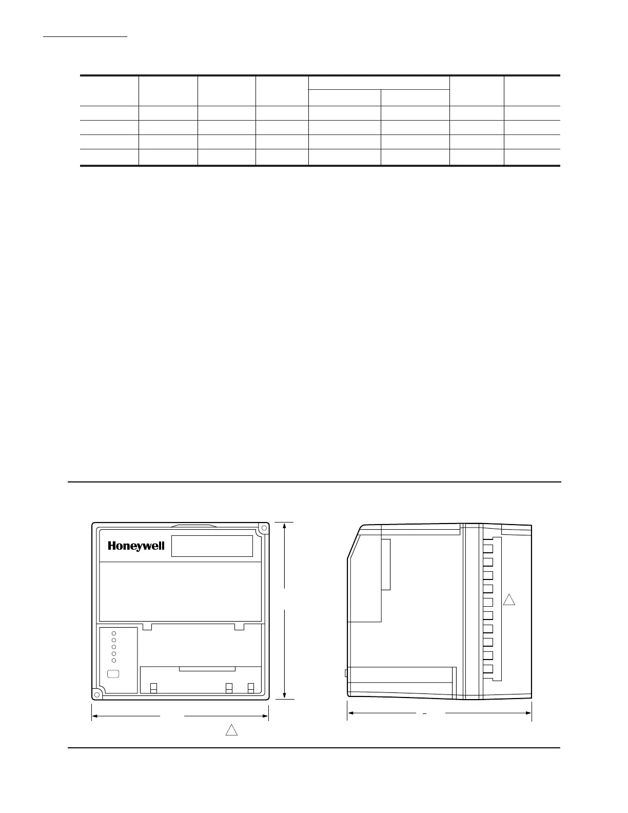
Fig. 1—Mounting dimensions of RM7895 Relay Module and Q7800A Subbase in inches [millimeters].
POWER
PILOT
FLAME
MAIN
ALARM
RESET
5
[127]
5 [127]
M5003A
5 [133]
1
4
BURNER CONTROL
REMOVE ONLY FOR TERMINAL TEST ACCESS.
1
1
RM7895A,B,C,D
SPECIFICATIONS
SEQUENCE TIMING FOR NORMAL OPERATION:
Flame Establishing Period
Device Initiate Standby Purge Pilot Main AFSC
1
DMV
2
RM7895A 10 sec. * ** 4 or 10 sec. No No No
RM7895B 10 sec. * ** 4 or 10 sec. No Yes No
RM7895C 10 sec. * ** 4 or10 sec.
3
10 sec. No Yes
RM7895D 10 sec. * ** 4 or 10 sec. 10 sec. Yes Yes
* STANDBY and RUN can be an infinite time period.
** PURGE will be determined by which ST7800A Purge Card is selected.
1
AFSC is Airflow Switch Check. Factory configured by model only.
2
DMV is Delayed Main Valve.
3
The RM7895C1020 (only) has a fixed pilot flame establishing period of ten seconds.
APPROVAL BODIES:
Underwriters Laboratories Inc. listed: File no. MP268,
Guide no. MCCZ.
Canadian Standards Association certified: LR9S329-3.
Factory Mutual approved.
International Approval Services (formerly AGA) Report
no. C2030002.
IRI acceptable.
Federal Communications Commission: Part 15, Class B—
Emissions.
MOUNTING: Q7800A for panel mount or Q7800B for
wall or burner mount.
REQUIRED COMPONENTS:
Plug-in Flame Signal Amplifier, see Table 2.
Plug-in Purge Timer Cards: selectable ST7800A: two
seconds to 30 minutes.
Q7800A or Q7800B.
ACCESSORIES:
Optional:
Communication Interface Base Unit, part no.
Q7700A1014.
Communication Interface ControlBus Module, part
no. QS7800A1001.
COMBUSTION SYSTEM MANAGER™, part no.
ZM7850A1001.
ControlBus 5-Wire Electrical Connector, part no.
203541.
DATA CONTROLBUS MODULE™, part no.
S7810A1009.
Dust Cover, part no. 221729A.
Expanded Annunciator, part no. S7830A1005.
Flame Simulators:
UV Flame Simulator, part no. 203659.
Rectification Simulator, part no. 123514A.
Keyboard Display Module, part no. S7800A1001.
Remote Display Mounting Bracket, part no. 203765.
Remote Display Power Supply, part no. 203968A
Plug-in.
Remote Reset Module, part no. 57820A1007.
Sixty-inch Extension Cable Assembly, part no.
221818A.
Tester, part no. A7800A1002.
 Loading...