EasyManuals Logo

Honeywell SDC 7-21 User Manual

Honeywell SDC 7-21
92 pages
To Next Page IconTo Next Page
To Previous Page IconTo Previous Page
Page #40 background imageLoading...
Page #40 background image
Connection of Room Devices SDC
40 MU1H-0438GE51 R0313
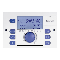
8.3 Wall Module SDW 10 / SDW 30
Configuration
Configuration of wall module SD 10 / SD 30 is done via parameter
03 of the heating- or mixing circuit on the controller. In addition, a
bus address must be selected at the wall module.
The assignment of a bus address occurs as follows:
Controller with bus address 10 (default) communicate with wall
modules having bus address 1 (for direct heating circuits, 2 (for
mixing circuit 1) or 3 (for mixing circuit 2).
SDW 10
bus address
Central controller
Heating circuit
No.
Bus address
1
1
10
Unmixed heating circuit
2
1
10
Mixed heating circuit 1
3
1
10
Mixed heating circuit 2
4
2
20
Unmixed heating circuit
5
2
20
Mixed heating circuit 1
6
2
20
Mixed heating circuit 2
7
3
30
Unmixed heating circuit
8
3
30
Mixed heating circuit 1
9
3
30
Mixed heating circuit 2
A
4
40
Unmixed heating circuit
B
4
40
Mixed heating circuit 1
C
4
40
Mixed heating circuit 2
D
5
50
Unmixed heating circuit
E
5
50
Mixed heating circuit 1
F
5
50
Mixed heating circuit 2
0
undefined
undefined
Bus address
assignment

Table of Contents

Questions and Answers:

Question and Answer IconNeed help?

Do you have a question about the Honeywell SDC 7-21 and is the answer not in the manual?

Honeywell SDC 7-21 Specifications

General IconGeneral
BrandHoneywell
ModelSDC 7-21
CategoryNetwork Router
LanguageEnglish

Related product manuals