T775A/B/M SERIES 2000 ELECTRONIC STAND-ALONE CONTROLLERS
62-0254—13 18
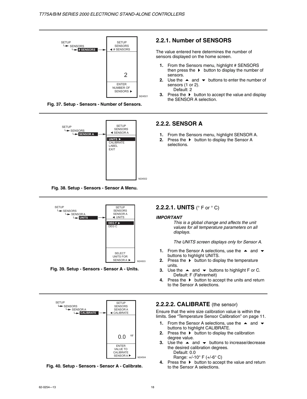
Fig. 37. Setup - Sensors - Number of Sensors.
2.2.1. Number of SENSORS
The value entered here determines the number of
sensors displayed on the home screen.
1. From the Sensors menu, highlight # SENSORS
then press the
button to display the number of
sensors.
2. Use the
and buttons to enter the number of
sensors (1 or 2).
Default: 2
3. Press the
button to accept the value and display
the SENSOR A selection.
Fig. 38. Setup - Sensors - Sensor A Menu.
2.2.2. SENSOR A
1. From the Sensors menu, highlight SENSOR A.
2. Press the
button to display the Sensor A
selections.
Fig. 39. Setup - Sensors - Sensor A - Units.
2.2.2.1. UNITS (° F or ° C)
IMPORTANT
This is a global change and affects the unit
values for all temperature parameters on all
displays.
The UNITS screen displays only for Sensor A.
1. From the Sensor A selections, use the
and
buttons to highlight UNITS.
2. Press the
button to display the temperature
units.
3. Use the
and buttons to highlight F or C.
Default: F (Fahrenheit)
4. Press the
button to accept the units and return
to the Sensor A selections.
Fig. 40. Setup - Sensors - Sensor A - Calibrate.
2.2.2.2. CALIBRATE (the sensor)
Ensure that the wire size calibration value is within the
limits. See “Temperature Sensor Calibration” on page 11.
1. From the Sensor A selections, use the
and
buttons to highlight CALIBRATE.
2. Press the
button to display the calibration
degree value.
3. Use the
and buttons to increase/decrease
the desired calibration degrees.
Default: 0.0
Range: +/-10° F (+/-6° C)
4. Press the
button to accept the value and return
to the Sensor A selections.
ENTER
NUMBER OF
SENSORS
SETUP
SENSORS
# SENSORS
SETUP
SENSORS
# SENSORS
2
M24501
 Loading...


