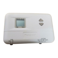
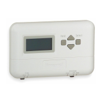
T8400C ELECTRONIC THERMOSTAT
1
5_£ET
[1,5METERS]
!
J
J
i
/
/
Fig. 1, Typical location of thermostat.
_ DR_LL 3/_6 INCH HOLgS 0g DRYWALL/OR 7/32 (PLASTER OR WOOD)
WHEN USING WALL ANCHORS
M1_88
Fig. 2. Mounting wallplate to wall.
Wiring
IMPORTANT
Use an 18-gauge maximum wire for wiring the
T840gC Thermostats
AII wiring must comply with local electrical codes and
ordinances Disconnect the power supply to prevent
electrical shock or equipment damage
NOTE: To ensure proper mounting of thermostat,
restrict aft wiring to the shaded area on the left
side of the terminals See Fig. 3
The shape of the terminals permits insertion of straight or
wraparound wiring connections; either method is
acceptable See Fig 4.
The T84000 Thermostat is powered through the heating/
cooling system controls and is adaptable to most 4-wire,
18 to 30 Vac heating-cooling systems Refer to Fig 5 and
6 for typical wiring hookups.
- KEEPW_R_NGIN
SHADEDAREAf-- ALTERNATEMOUNT_NG
/ SCREW_€gLE
SCREW
HOLE
MOUNTING
SCREWHOLE
_""_L W_I_]NG ENTRANCE HOLE
MOUNTING Ml1023
SCRBWHOlE
Fig. 3. Restrict wiring to shaded area,
69-1485-1 2

 Loading...