EasyManua.ls Logo

Honeywell ELECTRONIC THERMOSTATS T8401C User Manual

Honeywell ELECTRONIC THERMOSTATS T8401C
8 pages
To Next Page IconTo Next Page
Page #1 background imageLoading...
Page #1 background image
® U.S. Registered Trademark
Copyright © 2002 Honeywell • • All Rights Reserved
INSTALLATION INSTRUCTIONS
69-1483-1
T8401C
Electronic Thermostats
APPLICATION
The T8401C Thermostat provides single-stage,
nonprogrammable
temperature control for 24 Vac heating
cooling systems with manual changeover from heat to
cool. Heating cycle rate is selectable at 1, 3, 6, 9 or 12
cph. Cooling cycle reate is fixed at 3 cph. Temperature
indicature indication can be set for °F or °C.
The T8401C1031 (Fig. 1) is powered directly from the
zone panel. Batteries are not required because setpoints
are held permanently by non-volatile memory.
T8401C models include a thermostat, wallplate (for
wiring and mounting thermostat) and owner’s guide. See
Table 1 for a listing of thermostat features. See Table 2
for a listing of zone panels that can be used with the
T8401C.
Fig. 1. The T8401C1031 Thermostat.
MERCURY NOTICE
If this control is replacing a control that contains
mercury in a sealed tube, do not place your old
control in the trash. Dispose of properly.
Contact your local waste management authority
for instructions regarding recycling and the
proper disposal of an old control.
INSTALLATION
When Installing this Product…
1. Read these instructions carefully. Failure to follow
them could damage the product or cause a hazard-
ous condition.
2. Check the ratings given in the instructions and on
the product to make sure the product is suitable for
your application.
3. Installer must be a trained, experienced service
technician.
4. After installation is complete, check out product
operation as provided in these instructions.
CAUTION
Damage to Heating/Cooling System Possible.
Be careful when handling wires during
installation. Disconnect power at furnace or main
breaker/ fuse box.
Location
Install the thermostat about 5 ft (1.5m) above the floor in
an area with good air circulation at average temperature.
See Fig. 2. Do not install the thermostat where it can be
affected by:
drafts or dead spots behind doors and in corners.
hot or cold air from ducts.
radiant heat from the sun or appliances.
concealed pipes and chimneys.
unheated (uncooled) areas such as an outside wall
behind the thermostat.
M14752
FAN SYSTEM
Auto On
Cool Off Heat
Set
Room
Table 1. Thermostat Features
Model Powering Method Changeover System Selection Fan Selection
T8401C1031 Hardwired Manual Heat-Off-Cool On-Auto
Question and Answer IconNeed help?

Do you have a question about the Honeywell ELECTRONIC THERMOSTATS T8401C and is the answer not in the manual?
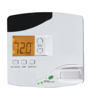
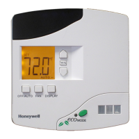
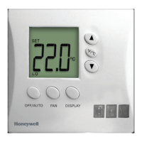
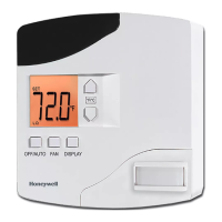
Honeywell ELECTRONIC THERMOSTATS T8401C Specifications

General IconGeneral
DisplayDigital
Stages1 Heat / 1 Cool
Voltage Rating24V AC
DifferentialAdjustable
Switch ActionSPDT
TypeElectronic
Temperature Range40°F to 90°F (4°C to 32°C)
Power SourceBattery
Power MethodBattery
MountingWall Mount
CompatibilitySingle-stage cooling and heating systems

Summary

Product Overview and Installation

T8401C Thermostat Application

Single-stage, nonprogrammable temperature control for 24 Vac heating/cooling systems.

General Installation Guidelines

Follow instructions carefully, check product ratings, use trained technician, and test.

Installation Safety and Location

Disconnect power before wiring, install 5 ft high, avoid drafts, direct sun, and unheated areas.

Mercury Disposal Notice

Proper disposal of old controls containing mercury is required; do not trash.

Wallplate Mounting

Wallplate Mounting Procedure

Place wallplate, pull wire through, select mounting holes, fasten securely, and seal openings.

Wallplate Mounting Notes

Leveling is for appearance only; thermostat functions normally even when not level.

Settings and Wiring

Fan Operation Switch Settings

Switch 'F' for most systems, 'E' for electric heat systems to turn fan on with heating/cooling.

Wiring Guidelines and Connections

Use 18-gauge cable, comply with codes, disconnect power, restrict wiring to shaded area.

Thermostat Mounting and Removal

Mounting Thermostat to Wallplate

Engage top tabs, then swing down and press lower edge to latch securely.

Removing Thermostat from Wallplate

Pull lower edge away from wall, swing up to detach.

Detailed Settings and Adjustments

Setting FAN and SYSTEM Switches

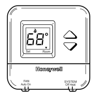
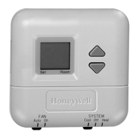
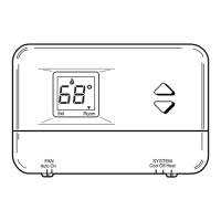
Manually control fan and system settings using switches at the thermostat bottom.

Fan and System Switch Operation

Details on 'On'/'Auto' fan and 'Cool'/'Off'/'Heat' system switch functions.

Setting °F/°C and Heat Cycle Rate

Guides for changing temperature units and heat cycle rate using specific steps.

System Checkout and Setup

Optional System Checkout Procedure

Use keys to turn heat/cool outputs on/off for testing system functions.

Installer Setup Mode Features

Access via simultaneous key press to set revision code, factory info, °F/°C, and cycle rates.

Checkout Procedures

Heating and Cooling Checkout

Test heating by raising setpoint, test cooling by lowering setpoint.

Fan Checkout Procedure

Test fan operation by setting SYSTEM to Off/On and FAN to On/Auto.

Related product manuals