Do you have a question about the Honeywell E529.RF and is the answer not in the manual?
Instructions on how to mount the e529.RF thermostat, including plate separation and attachment.
Safety warnings, installer requirements, and guidelines for optimal device placement.
Detailed steps to enter the e529.RF thermostat's Service Mode for setting parameters.
Explanation of parameters like rId, PAn, rF, Adr, Io, SEr, and Loc for device configuration.
Overview of the commissioning process for different scenarios and device binding.
Steps to test general thermostat functions like display, temperature, and mode changes.
Procedures to test IRAS and RF network connectivity using PING and RUN menu.
Compliance statement for FCC rules regarding digital devices and radio frequency energy.
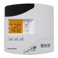
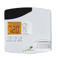
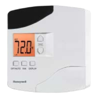
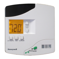
The Honeywell E529.RF Thermostat is a battery-operated device designed to work with an HVAC controller to monitor and maintain room temperature. It can also control other devices. The thermostat is primarily used in three scenarios: as part of a basic IRAS application communicating wirelessly with another device, as an IRAS application with RF communication to a network backbone, or as an IRAS application with wired communication to a network backbone.
The E529.RF's core function is to provide temperature control and monitoring within a room. Its battery-operated nature offers significant flexibility in placement, making it suitable for various fan coil units, heat pumps, or packaged terminal air conditioners commonly found in guestrooms. The device relies heavily on RF communication for its operation, which necessitates careful consideration of its placement to avoid radio interference. It should not be placed too close to the floor or ceiling, or near pipes or other metal objects, to ensure optimal performance. To maintain accurate room temperature measurements, the thermostat should be located away from external doors, windows, and areas exposed to direct sunlight, as these can introduce external interference.
The E529.RF is designed for ease of use and installation. To install the device, the E529.RF body and its mounting plate must first be separated by pulling the bottom of the mounting plate away from the body and then pulling the plate downwards. It's important to note that rotating the back-mounting plate more than 2 or 3 degrees can cause the plastic tabs at the top to fracture or break. The mounting plate is then attached to the wall or an electrical box, ensuring the embossed arrow points upward. Four 6-32 3/4" sheet metal screws are provided for mounting to an existing 4" x 4" electrical box. For sheetrock or similar wall surfaces, four 6-8 × 3¼ anchors should be used, and the mounting plate holes can serve as markers for their placement.
Powering the device involves installing four AA alkaline batteries (alkaline batteries only) into the battery compartment on the rear of the E529.RF. The battery clamp latch at the top of the compartment needs to be depressed, and the clamp swung open. The batteries are inserted, matching the "+" terminals to the "+" symbols in the compartment. After closing the battery clamp and ensuring the latch is securely fastened, the E529.RF display should show information. If the display is blank, users should verify that the batteries are correctly installed with the right polarities and are not dead.
Once powered, the E529.RF housing is hooked onto the mounting plate by aligning the tabs at the top rear of the housing with the depressions on the plate. The housing is then rotated towards the wall until it snaps into place. Finally, two small screws provided with the E529.RF secure the housing to the mounting plate, threading into two small holes at the bottom of the housing.
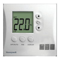
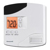
The thermostat features a "Service Mode" for installation technicians to set various parameters. This mode allows for unique room identification, binding INNCOM devices in the room, setting operational characteristics, and connecting the room to a floor- or building-wide network if needed. To enter Service Mode, users press and hold the °F/°C button, then press and release the OFF/AUTO button, press and release the DISPLAY button, and finally release the °F/°C button.
Within Service Mode, several parameters can be configured:
The E529.RF also includes built-in tests accessible through the "run" menu in Service Mode:
For operational control, users can:
The E529.RF is designed for indoor use only, and installation must be performed by a trained, experienced service technician. All wiring must comply with local codes and ordinances. Failure to follow instructions can damage the product or create hazardous conditions.
Regular verification of the E529.RF's display is important. If the display is blank, checking the battery installation and charge is the first step in troubleshooting. The device also includes a "PnG" (Ping) function in Service Mode, which sends a signal to connected devices and registers their response. This allows technicians to verify communication with the E529.RF. After a device has been pinged, pressing DISPLAY allows entry into the NVRAM of partner devices, though this should only be used by INNCOM technicians due to potential functionality impacts.
For testing IRAS and RF network connections, the PING parameter can be used to test each device on the network. The E529.RF LCD displays a dot in the lower right corner of the screen to indicate an RF link to the HVAC partner. Running test value 2 from the RUN menu executes an IWAN test; a successful test will show the Room ID scrolling across the LCD, indicating communication with the server.
To address potential radio interference, users are encouraged to:
| Type | Wireless |
|---|---|
| Programmability | Programmable |
| Power Source | Battery-Powered |
| Communication | Wireless (RF) |
| Compatibility | Compatible with Honeywell RF heating systems |
| Display | Digital |
| Temperature Control | Digital |