T841A HEATING-COOLING THERMOSTATS
THERMOSTAT
___
A
_____
SUBBASE
__
A ___
A / -
SYSTEM COMPONENTS
______
A
________
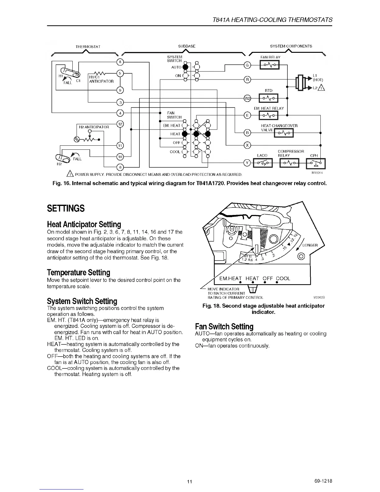
Fig. 16. Internal schematic and typical wiring diagram for T841A1720. Provides heat changeover relay control.
SYSTEM
SETTINGS
Heat Anticipator Setting
O n m o d el s h ow n in Fig. 2, 3, 6, 7, 8, 11, 14, 16 and 17 the
secon d s tage heat an tic ip ato r is a d ju stab le. On these
m o d e ls , m o ve th e a dju sta b le in dicator to m atch the curre n t
d raw o f the s e c o n d sta g e h e a ting p rim ary c o ntro l, o r the
a n ticip a to r s e tting of th e o ld th e rm osta t. See Fig. 18.
Temperature Setting
M o ve the s e tp o in t le v er to th e d esire d c o n tro l p o int on the
te m p e ra ture scale.
System Switch Setting
The s y s te m s w itc h in g p o sition s c o n tro l the syste m
o p e ra tio n as follow s.
EM. HT. (T 84 1 A o nly)— e m erge n cy heat re la y is
ene rg ized. C o olin g s y s te m is off. C o m pre sso r is d e
ene rg ized. F an run s w ith call fo r heat in A U T O p osition.
EM. HT. LED is on.
H E A T — h e a ting system is a u tom atica lly c o n tro lle d b y the
therm osta t. C ooling system is off.
O F F — b oth th e h eatin g a nd coolin g s yste m s are off. If the
fan is at A U TO p osition, the cooling fan is a lso off.
C O O L— cooling syste m is a u to m atic a lly co n trolle d by the
therm osta t. H e a tin g system is off.
Fig. 18. Second stage adjustable heat anticipator
indicator.
Fan Switch Setting
A U T O — fan o p e ra tes a u to m a tica lly a s heating o r c o oling
e q u ip m e nt cy c le s on.
O N— fa n o pera tes c o n tinuou sly.
11
69-1218
 Loading...