S. M. • Rev. 5-93 • • ©Honeywell Inc. 1993 • Form Number 60-1147—4
T874/Q674
Thermostat/Subbase Combinations
Installation Instructions for the Trained Service Technician.
Application
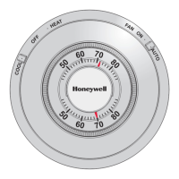
The T874/Q674 Thermostat/Subbase combinations provide 24 to 30 Vac control for heat pump systems. See Table 1.
TABLE 1—T874/Q674 THERMOSTAT/SUBBASE COMBINATIONS.
Thermostat/ Number Changeover
Subbase
a
of Stages Stage Type of Switching
Model Heating Cooling Heating Cooling System Fan See Fig.
T874N/Q674C 2 1 1 — OFF-AUTO AUTO-ON 5
T874N/Q674F 2 1 — 1 OFF-EM. HT.- AUTO-ON 6
HEAT-AUTO-COOL
T874R/Q674L 2 1 — 2
b
EM. HT.-HEAT- AUTO-ON 7
OFF-COOL
a
Q674 Subbase provides the wiring terminals, system switch and fan switch for system operation.
b
Provides manual changeover with the subbase system switch in COOL position.
Installation
WHEN INSTALLING THIS PRODUCT…
1. Read these instructions carefully. Failure to follow
them could cause a hazardous condition.
2. Check the ratings given in the instructions and on the
product to make sure the product is suitable for your applica-
tion.
3. Installer must be a trained, experienced service tech-
nician.
4. After installation is complete, check out product opera-
tion as provided in these instructions.
CAUTION
1. Disconnect power supply to prevent electrical
shock and equipment damage.
2. To prevent interference with the thermostat link-
age, keep wire length to a minimum and run
wires as close as possible to the subbase. Push
excess wire back into the hole and plug hole to
prevent drafts from affecting thermostat opera-
tion.
3. Do not overtighten thermostat captive mounting
screws because damage to subbase threads may
result.
4. Do not short across coil terminals on the relay.
This may burn out the thermostat heat
anticipator.
IMPORTANT: Thermostats are calibrated at the factory
using subbases mounted at true level. An inaccurately
leveled subbase will cause thermostat control devia-
tion.
Operation
On a two-heat thermostat, the two stages of heat make
sequentially as the temperature drops. Make refers to the
mercury switch initiating a call for heat or cool.
There are about 2° F [1° C] between stages so that the
second stage makes only when the first stage cannot handle
the load. This is the interstage differential.
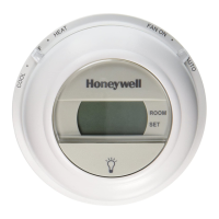
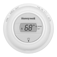
One or two LEDs (light emitting diodes) are included on
your subbase. Refer to the list below for specific meaning.
The CHECK LED lights when something needs to be
checked or done to maintain efficient operation of the system.
See your heating system instructions for the specific mean-
ing.
The EM. HT. LED lights when the system switch is placed
in the EM. HT. position. Emergency heat is operating; in
most systems, the compressor has failed and the heat pump
is not operating.
The AUX. HT. LED lights when the auxiliary heat stage
is operating. The weather is cold enough that the first stage
cannot handle the load alone.
LEDs are not field replaceable or addable.
M3375
M3375
Recycling Notice
This control contains mercury in a sealed tube. Do not
place control in the trash at the end of its useful life.
If this control is replacing a control that contains mercury in
a sealed tube, do not place your old control in the trash.
Contact your local waste management authority for in-
structions regarding recycling and the proper disposal of this
control, or of an old control containing mercury in a sealed
tube.
If you have questions, call Honeywell at 1-800-468-1502.