3 69-0753
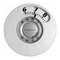
TEMPERATURE LEVER STOPS
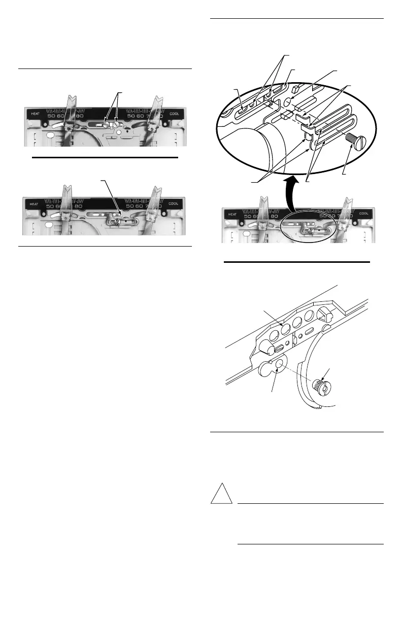
The T874D has factory-installed temperature lever lock-
ing screws and stop brackets. See Figs. 6 and 7. These
should be used only if the HEAT and COOL temperature
setpoint lever ranges are to be restricted.
Fig. 6—Location of locking lever screws.
Fig. 7—Location of lever stop brackets.
INSTALL AND ADJUST LOCKING LEVER
SCREWS
The two screws with insulated heads should be used
only if the HEAT and COOL levers are to be locked in
place at a specific temperature control point. Do not use
standard screws that provide metal-to-metal contact with
the lever brackets.
To install:
1. Refer to Fig. 8 for screw hole locations.
2. Install the two screws with insulated heads in the
indicated holes Do not overtighten screws.
3. Set the HEAT lever and the COOL lever at desired
temperature control points.
4. Firmly tighten both screws.
INSTALL AND ADJUST STOP BRACKETS
The stop brackets should be installed only if there is a
need to restrict the adjustable range of the heating and
cooling temperature setpoint levers. See Fig. 6.
To install:
1. Turn over the T874 Thermostat to the back side.
Locate the hole in the plastic base for the brass insert. See
Fig. 9.
Fig. 8—Installing locking lever screws and stop
brackets.
2. Push brass insert into the hole with your finger.
3. Turn to front side of the T874 Thermostat.
4. Place the two stop brackets in position with the tabs
in the slot between the HEAT and COOL levers. See Fig. 8.
5. Insert the mounting screws into the two slots in the
stop brackets and attach to the brass insert. Tighten the
screw to pull the brass insert into the back of the thermostat.
6. Loosen the mounting screw enough to slide the stop
brackets for adjustment.
7. Move the HEAT and COOL setpoint levers to the
maximum temperature that is desired.
8. Slide the stop brackets until one rests against the
HEAT lever and the other against the COOL lever.
Fig. 9—Installing brass insert.
LED WINDOW
BRASS INSERT
INSERT HOLE
BACK OF
THERMOSTAT
M955A
9. Firmly tighten the mounting screw.
10. If the HEAT and COOL levers are to be locked in
place at a specific temperature, use the two insulated head
screws supplied instead of the two adjustable lever stop
brackets.
CAUTION
Do not use standard screws that provide metal-to-
metal contact with the stop brackets. Short cir-
cuit and potential equipment damage may re-
sult.
M7346
HEAT
LEVER
HOLES FOR INSULATED
LOCKING LEVER SCREWS
COOL
LEVER
HOLE WITH
BRASS INSERT
BRACKET
TABS
ADJUSTABLE
LEVER STOP
BRACKETS
BRACKET
SLOTS
MOUNTING
SCREW
LEVER LOCKING SCREWS
M18680
LEVER STOP BRACKETS
M18681

 Loading...