5 69-0753
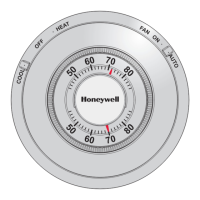
Fig. 12—Location of external components.
M3459
FAN
SWITCH
SYSTEM
SWITCH
OFF
AUTO
FAN
HEAT
ON
AUTO
COOL
1.2
.8
.6
.3
.2
1.5
.4
50 60
70 80
HEAT
HEATING SET
POINT LEVER
50 60
70 80
HEAT
COOLING SET
POINT LEVER
1.2
.8
.6
.3
.2
1.5
.4
.12
SUBBASE SETTING
The subbase switching positions control the system
operation as follows (see Fig. 12):
SYSTEM SWITCH (some subbase do not have all of the
following functions):
OFF—both the heating and cooling systems are off. If
the fan switch is in AUTO position, the cooling fan is
also off.
HEAT—heating system is automatically controlled by
the thermostat. Cooling system is off.
AUTO—thermostat automatically changes between
heating and cooling system operation, depending on
the indoor temperature.
COOL—cooling system is automatically controlled by
the thermostat. Heating system is off.
FAN SWITCH
ON—fan operates continuously.
AUTO—fan operates with cooling equipment as con-
trolled by the thermostat or with the heating equip-
ment as controlled by the plenum switch.
To move the subbase switches to the desired control
positions, use thumb and index finger to slide lever. Lever
must stop over desired function indicator position for
proper circuit operation.
Checkout
HEATING
Move the system switch on the Q674 to HEAT or
AUTO, and the fan switch to AUTO. Move the heating
setpoint lever on the T874 about 10° F [6° C] above room
temperature. Heating equipment should start and the fan
should run. Move the heating lever about 10° F [6° C]
below room temperature. The heating equipment and fan
should shut off.
NOTE: In heat pump applications, a minimum off-timer
provides a five-minute time delay before starting com-
pressor when the thermostat last turned off the compres-
sor, or when the system first received power. This delay
prevents compressor short cycling.
COOLING
CAUTION
If outside air or heat exchange medium (water) is
below 50° F [10° C], do not operate cooling.
Move the system switch on the Q674 to COOL or AUTO,
and the fan switch to AUTO. Move the cooling setpoint
lever on the T874 about 10° F [6° C] below room tempera-
ture. The cooling equipment should start (see Note). Move
the cool lever about 10° F [6° C] above room temperature.
The cooling equipment and fan should shut off.
NOTE: If using a Control Module Mark IV, there are
time delays built-in. Check your Mark IV instructions
for specifics.
FAN
Move the subbase system switch to OFF, and the fan
switch to ON. The fan should run continuously. Move the
fan switch to AUTO. In this position, fan operation is
controlled by the heating or cooling system control circuit.
INSTALL OR REMOVE TG504A KEY LOCK
COVER
To install the TG504A:
—hang the upper edge of the cover on the thermostat
subbase.
—swing cover downward.
Spring-loaded locking mechanism will automatically
engage mounting posts and secure cover in final position
without use of key provided.
To remove the TG504A:
— insert the key provided.
— rotate the key clockwise until locking mechanism
releases from thermostat posts.
— swing cover upward and off.
Calibration
THERMOSTAT
T874 Thermostats are accurately calibrated at the fac-
tory. They do not have provision for field calibration.

 Loading...