H200-501-00 I56-4409-002
Honeywell Building Solutions, Honeywell House, Arlington Business Park, Bracknell, Berkshire, RG12 1EB, UK
DOP-IOD086
EN 54-17: 2005
EN 54-18: 2005
60°C
Honeywell Control Systems Ltd
Honeywell House
Arlington Business Park
Bracknell, Berkshire
RG12 1EB, UK
0359 23
0905 21
This manual is intended as a quick reference installation guide. Please refer to the
control panel manufacturers installation manual for detailed system information.
The Honeywell series of modules are a family of microprocessor controlled
interface devices permitting the monitoring and/or control of auxiliary devices. The
TC810E1032A is an output module that allows the control of auxiliary devices such
as re shutters or sounders.
A single tri-colour LED indicates the status of the module. In normal conditions, the
LED can be set by command from the control panel to blink green when the module is
polled. When the control panel switches the relay to the energised state the LED can
be set to continuous green.
SPECIFICATIONS
Operating Voltage Range: 15 to 32 VDC (Min 16.5 VDC for LED operation)
Maximum Standby Current 160 µA - No Communication
LED Current (Red): 1.5 mA
LED Current (Yellow): 5.5 mA
Isolator features: see S00-7100
Humidity: 5% to 95% relative humidity (non-condensing)
Maximum Wire Gauge 2.5 mm²
INSTALLATION
Note: These modules must only be connected to control panels using compatible
proprietary analogue addressable communication protocols for monitoring and control.
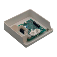
Honeywell series modules can be mounted in several ways (See Figure 1):
1:1 An M200E-SMB custom low prole surface-mounting box. The SMB Base is
axed to mounting surface, and then the module and cover are screwed onto
the base using the two screws supplied. Box dimensions: 132 mm (H) x 137 mm
(W) x 40 mm (D)
1:2 The DIN bracket on top allows mounting onto standard 35 mm x 7.5 mm "Top Hat"
DIN rail inside a control panel or other suitable enclosure. Install and remove as
shown in Figure 1:2.
Wiring to all series Honeywell modules is via plug in type terminals capable of
supporting conductors up to 2.5 mm²
CAUTION
Disconnect loop power before installing modules or sensors.
The module address is selected by means of rotary decade address switches (see
Figure 4). A screwdriver should be used to rotate the wheels to select the desired
address, either from the front or the top of the module. (Note: The number of addresses
available will be dependent on panel capability, check the panel documentation for
information on this.)
Short Circuit Isolators
All Honeywell series modules are provided with short circuit monitoring and isolators
on the intelligent loop. If required the isolators may be wired out of the loop to facilitate
the use of the modules on high current loaded loops, for example if sounders are
used. To achieve this, the loop out positive should be wired to terminal 5 rather than
terminal 2. See the relevant wiring diagram for details.
TC810E1032A WIRING
The TC810E1032A can be wired for either Supervised (Figure 2) or Non-Supervised
(Figure 3) operation respectively.
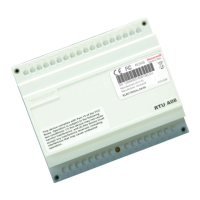
TC810E1032A
INSTALLATION INSTRUCTIONS
FOR THE TC810E1032A OUTPUT MODULE
EN
TC810E1032A Single Output Module with Supervised Output
When the module is used in supervised mode and power is supplied to the module,
a switched negative input on terminal 12 can be used to signal an external fault
condition, such as a power supply fault. Loss of power is also supervised in this mode
such that if the supply voltage falls below 7 V a fault indication is achievable. Note that
the use of this fault mode is dependant on panel software. Please contact the panel
manufacturer for further details.
PSU monitoring is not available when the module switches the output to Alarm.
Wire as follows (see Figure 2):
a: T1 Loop Output -. b: T2 Loop Output +. c: T3 Loop Input -. d: T4 Loop Input +
e: T5 Loop Output +. If short circuit isolation is not required, loop output+ should be
wired to terminal 5 and not 2. Terminal 5 is internally connected to terminal 4.
f: To enable output circuit supervision, the link supplied must be tted across
terminals 6 and 7, and the load must be polarised.
TC810E1032A
TC810E1032A
CAUTION
Electrostatic Sensitive Device
Observe precautions when handling and making connections
Fig./Abb. 4
+
(i)
(ii)
(iii)
Fig./Abb. 2
Fig./Abb. 3
Fig./Abb. 5
Lift
Sollevare
Levantar
Anheben
Push down
Premere
Precionar
hacia abajo
Runterdrücken
Rotate / Ruotare
Girar / Drehen
Rotate
Ruotare
Girar
Drehen
Clip / Agganciare
Acoplar / Einrasten
Plug
Inserire
Conectar
Einhaken
2
3
1
13
2
1:2 DIN
1:1 M200E-SMB
Fig./Abb. 1