Home
Honeywell
Control Unit
TC Series
Honeywell TC Series User Manual
4
of 1
of 1 rating
55 pages
Give review
Manual
Specs
To Next Page
To Next Page
Loading...
3
E
d
i
t
i
o
n
0
8
.
17
AGA
T
echnical Infor
m
ation · G
B
•
Adjustable test pe
riod which can be adapted to d
if
ferent s
ys
tems
•
Adjustable test inst
ant allows quic
k sys
tem st
ar
t
•
Maximum sa
fet
y thanks to self
-monitori
ng elec
tronics
T
ightne
s
s
cont
rol
s TC
Safe
t
y manual for produc
t
s comply
ing wi
th E
N 6150
8
2
2
Table of Contents
Tightness Controls TC
1
Contents
2
Table of Contents
2
1 Application
4
Application Examples
7
TC 1V with Valvario Controls
7
TC 1C with Combination Control CG
8
TC 2 with Two Gas Solenoid Valves
9
Auxiliary Valve for Discharge
10
Auxiliary Valve for Discharge
11
TC 2 in a Multiple Burner System with Several
12
Valves Installed in Series
12
Valves Installed in Series
13
TC 4 with Two Gas Solenoid Valves
14
Auxiliary Valve for Discharge
15
TC 4 in a Multiple Burner System with Two Auxiliary Valves for Supply and Discharge
16
Valves Installed in Series
17
2 Certification
18
Tc 1, Tc 2, Tc 3
18
Tc 4
19
3 Function
20
Tc 1, Tc 2, Tc 3
20
Connection Diagrams for TC 1, TC 2
20
Connection Diagrams for TC 3
21
Test Procedure for TC 1, TC 2, TC 3
22
Test Instant TC 1, TC 2, TC 3
24
Test Instant for Mode 1: Testing before Burner Run
24
Test Instant for Mode 2: Testing after Burner Run
25
Test Instant for Mode 3: Testing before and after
26
Burner Run
26
Measurement Time T M for TC 1, TC 2, TC 3
27
Calculation Example for T M
27
Tc 4
28
Connection Diagram
28
Test Procedure TC 4
29
TC 4 Test Instant
31
Test Instant for Mode 1: Testing before Burner Run
31
Test Instant for Mode 2: Testing after Burner Run
32
For TC 4
33
Calculation Example for T P
33
Test Volume V P for TC 1, TC 2, TC 3, TC 4
34
Leakage Rate Q L
35
Animation
36
Selection
37
Tc 1, Tc 2, Tc 3
37
Selection Table
37
Type Code
37
4 Selection
37
Tc 4
37
5 Project Planning Information
38
Selecting the Auxiliary Valves
38
Start Rate
39
Installation
39
TC 1V for Solenoid Valves for Gas VAS, VCX
39
TC 1C for Combination Controls CG
39
TC 2..R: Rp ¼
40
TC 3..R: Rp ¼
40
Tc 4
40
Electrical Connection of TC 1, TC 2
41
Determining the Relief Line Size
41
6 Accessories
42
Socket
42
Valve Connection Cable
42
External Pressure Switch for TC 4
42
7 Technical Data
43
Tc 1, Tc 2, Tc 3
43
Tc 4
44
Indicators and Operating Controls
46
Dimensions
47
Converting Units
47
Safety-Specific Characteristic Values
48
8 Safety Information in Accordance with
49
EN 61508-2 for TC 1, TC 2, TC 3
49
General
49
Type of Action
49
Other Classifications
49
Electrical Data
49
Interfaces
50
Electrical Wiring
50
Connection Terminals
50
Inputs
50
Outputs
51
SIL and PL for TC 1, TC 2, TC 3
51
9 Maintenance Cycles
52
10 Glossary
53
Tightness Control
53
Valve Proving System VPS
53
Safety Interlocks
53
Diagnostic Coverage DC
53
Operating Mode
53
Hardware Fault Tolerance HFT
53
Probability of Dangerous Failure PFHD
54
Mean Time to Dangerous Failure MTTF D
54
Feedback
55
Contact
55
4
Based on 1 rating
Ask a question
Give review
Questions and Answers:
Need help?
Do you have a question about the Honeywell TC Series and is the answer not in the manual?
Ask a question
Honeywell TC Series Specifications
General
Category
Control Unit
Enclosure Rating
IP20
Input Voltage
24 VDC
Communication Protocol
Modbus RTU, BACnet MS/TP
Series
TC Series
Related product manuals
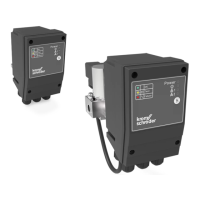
Honeywell Kromschroder TC 1
12 pages
Honeywell Kromschroder TC 2
12 pages
Honeywell Kromschroder TC 3
12 pages
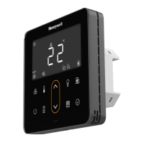
Honeywell TR80
78 pages
Honeywell TR120
32 pages
Honeywell TM3400
12 pages
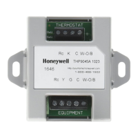
Honeywell THP9045
12 pages
Honeywell TR80UWD
78 pages
Honeywell TC810E1040
4 pages
Honeywell Temaline TK-S014
26 pages
Honeywell TrueZONE ARD Series
8 pages
Satronic TFI 812 Series
4 pages