TC · Edition 08.17 46
Technical data
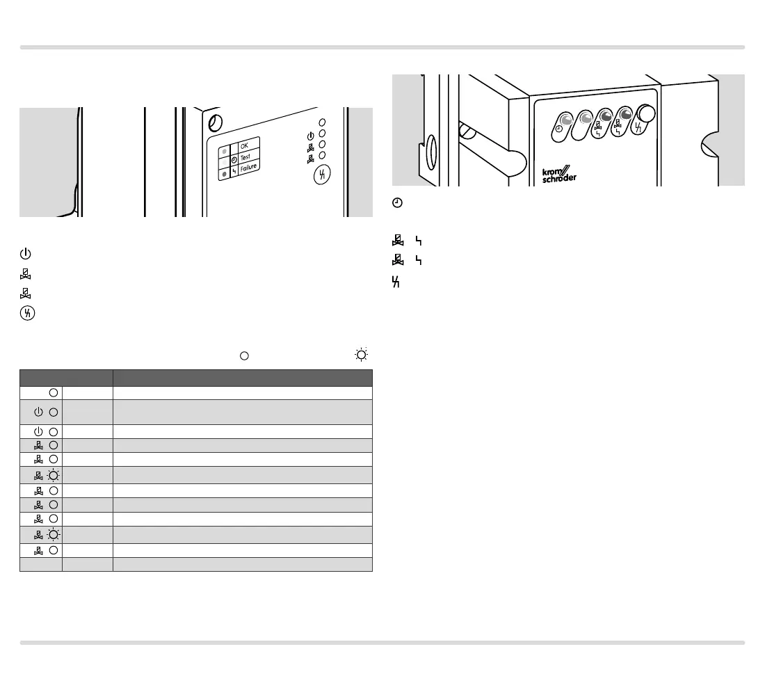
7.3 Indicators and operating controls
TC 1, TC 2, TC 3
1
2
Power
= power supply
= operating signal
1
= valve 1
= valve 2
= reset button
The LEDs can display messages using three colours
(green, yellow, red) and permanent
or flashing light
:
LED Message/Operating status
green Power supply OK
yellow
TC is ready for operation; safety interlock* input signal
interrupted
green
TC is ready for operation; active safety interlock* input signal
green V1 is tight
yellow V1 is untested
1
yellow Tightness test is running on V1
red V1 is leaking
green V2 is tight
yellow V2 is untested
2
yellow Tightness test is running on V2
red V2 is leaking
All yellow Initialization
* see page 53 (Safety interlocks).
TC 4
OK
TEST
1
2
TEST
= TEST phase (yellow)
= operating signal (green)
= fault valve 1 (red)
= fault valve 2 (red)
= reset button

 Loading...