WV4262B POWERED DAMPER WATER HEATER CONTROLS
69-2496—03 2
Humidity:
95% Relative Humidity at 104 °F (40 °C).
Approvals:
This device is certified by CSA International to the fol-
lowing ANSI Standards (see report 158158-
1701693): Z21.20, Z21.23, Z21.35, Z21.78, Z21.87,
and Z21.94
Dimensions
See Fig. 2.
Accessory Parts (Order
Separately)
—Mounting Bracket:
P/N 50044631: 3/4” NPT, 1” insulation, 2”
insertion.
P/N 50044362: 3/4” NPT, 2” insulation, 3”
insertion.
— Pilot Assembly: P/N Q3451A (See a Honeywell
Product Specialist for other options)
— TOD FVS (Therm-O-Disc) Flammable Vapor Sensor
or equivalent. Refer to specific OEM Water Heater
Service Manual for correct selection of sensor.
— See Honeywell product specialist for other
available accessories.
Table 1. Capacity of WV4262B.
a
Capacity based on 1000 Btu/ft
3
, 0.64 specific gravity natural gas at 1.47 in. wc pressure drop (37.3 MJ/meter
3
,
0.64 specific gravity natural gas at 0.37 kPa pressure drop).
b
Valves are guaranteed at only 77 percent of the rating.
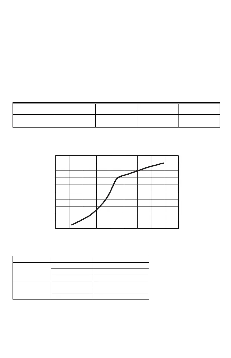
Fig. 1. Typical capacity curve for WV4262B Family Water Heater Control System.
Table 2. Gas Capacity.
Model
Size (Inlet x Outlet),
in.
Capacity (at 1.47 in.
wc pressure drop
a,b
)
Minimum
Regulated Capacity
Maximum
Regulated Capacity
WV4262B 1/2 NPT x 1/2
inverted flare
50 ft
3
/hr (3.7 m
3
/hr) 30 ft
3
/hr (0.6 m
3
/hr) 100 ft
3
/hr (5.1
m
3
/hr)
Gas Type Flow (kBTU/hr) Pressure Drop (in. w.c.)
NG
30 1.43
50 1.47
75 1.54
LP
30 0.91
50 0.94
75 0.97
CAPACITY
0
10
20
30
40
50
60
70
80
90
100
0.80.90.91.01.01.11.11.21.21.3
PRESSURE DROP
FLOW
M32315
 Loading...