(A)
(C)
(B)
(D)
(G)
(E)
(F)
(H)
IMPORTANT: This product is designed to give you years of reliable performance. Read the following instructions carefully before installing and/ or
operating the Smart Hitch Camera/ Sensor System. If you have any concerns with this product or the installation process, our technical
support team can assist you. Call 1-800-835-0129 8am-5pm CST, M-F.
Smart Hitch
™
Camera/Sensor System
1-800-835-0129 | www.HopkinsTowingSolutions.com
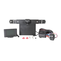
PARTS:
(A) 3.5” Color Monitor
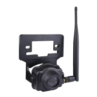
(B) Camera
(C) Mounting Bracket with Sensors
(D) Installation Cables
(E) 2 Cable Clips (optional)
(F) 2 License Plate Screws
(G) Grommet
(H) Connector
Possible monitor
mounting positions
(monitor appears larger for
illustration purposes)
FIGURE 1
STEP 1. Select monitor location, plan out the cable route, install the cables
WARNING:
DO NOT PLACE MONITOR WHERE AIR BAGS ARE LOCATED ON YOUR VEHICLE. Before selecting a location for the monitor please check to be
sure the monitor does not obstruct your view while driving.
Installation for Trucks
FIGURE 2
Locate the reverse light wire and splice the red
wire to the reverse light wire
TOOLS NEEDED:
- Screwdriver
- Drill (If Necessary)
- 11/32” Drill Bit
(If Necessary)
INSTALLATION GUIDE
1) Connect installation cable (D) to monitor (A) and route the installation cables (D) to the back of vehicle
stopping at the back side of the OEM connector on vehicle (Fig. 2).
NOTE: If additional length is needed call 800 835-0129.
2) Remove OEM plug from back side of the OEM connector on the vehicle.
3) Loosen gray tab, press down and pull out OEM plug on back side of connector.
4) Insert camera system OEM plug (H) into OEM connector. Secure gray tab.
For Vehicles WITHOUT OEM connector
For Vehicles WITH OEM 7 Blade Tow Package Connector -
(If your vehicle dos NOT have an OEM connector please skip to the “For Vehicles WITHOUT
OEM Connector” section)
1) Cut/Remove OEM plug (H)
2) Connect installation cable (D) to monitor (A) and route the wires to the reverse light assembly (Fig. 3).
NOTE: If additional length is needed call 800 835-0129.
3) Locate the reverse light wire and splice the red wire to the reverse light wire. (Fig 4)
4) Locate the common/ground wire behind the tail light assembly and splice the black wire to the ground wire.
5) Reassemble tail light assembly and secure wires out of the way. Place cable clips (E) where needed.
Place monitor (A) in desired location (dash or windshield) (Fig. 1) but do not permanently mount until later.
Installation for Vehicles with License Plate on Lift Gate
Installation for Trucks
FIGURE 3
STEP 2. Install the license plate bracket and camera
1) Remove license plate from the back of your vehicle
2) IMPORTANT: Unfold sensors from the back of the mounting bracket (C) and lock them in place. Ensure camera (b) is secured directly in the middle of the
main bracket. This will ensure “hitch mode” works perfectly with your hitch when hitching to your trailer.
3) Place the mounting bracket (C) behind the license plate and make sure license plate fits behind the sensors.
4) Some vehicles may have a hole available to pass the wire through where the license plate is mounted or you can drill 11/32” hole close to where the
power cable is attached to the mounting bracket (C). If you are going to drill a hole, remember to check the area to ensure nothing will be damaged behind
the bumper while drilling.
FIGURE 4