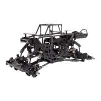
Do you have a question about the Horizon Hobby LOSI TLR TUNED LMT and is the answer not in the manual?
| Scale | 1/10 |
|---|---|
| Vehicle Type | Monster Truck |
| Drivetrain | 4WD |
| Shock Type | Oil-Filled |
| Drive System | Shaft-Driven |
| Gearbox | Single-Speed |
| Completion Level | Ready-to-Run (RTR) |
| Suspension | Solid Axle |
| Chassis | Aluminum |
| Motor | Brushless |
| ESC | Spektrum Firma 130A Smart ESC |
| Battery | LiPo (Not included) |
| Radio | Spektrum |
| Servo | Included |
| Differential | Locking |
| Body | Included |
Official instruction manual for the Losi TLR Tuned LMT 1/10 Kit, detailing assembly and operation.
Defines terms used to indicate potential harm levels during product operation.
Essential safety guidelines and warnings for operating the RC vehicle.
Lists essential components needed for the kit assembly.
Specifies necessary tools for building the RC vehicle.
Provides key physical dimensions and specifications for the model.
Explains the meaning of various icons used throughout the manual.
Assembly of differential components, applying grease.
Further assembly of differential housing with gears.
Installation of bevel gears and output shafts into the differential.
Assembly of differential components with grease and shafts.
Final assembly of differential gears and housing.
Assembling differential gears and housing with screws.
Filling the differential with 100k weight oil.
Tightening order for differential case screws.
Assembly of the center differential with gears and housing.
Assembly of differential components with gears and shafts.
Final assembly of differential gears and housing.
Assembly of differential gears and housing.
Filling the differential with 500k weight oil.
Tightening order for differential case screws.
Assembling front and rear adjustable linkages with threadlock.
Assembling upper and lower 4-link rods with threadlock.
Assembling shock bodies, collars, and spring retainers.
Attaching shock shafts to lower mounts.
Connecting shock shafts to shock bodies.
Filling shock bodies with 40WT oil.
Bleeding air from the shock assembly.
Compressing shock shafts for oil distribution.
Attaching shock ends to the assembly.
Installing oil seals and shock collars.
Installing shock springs and pistons.
Completing shock assembly with spring retainers.
Attaching front gearbox housing to the chassis.
Assembling differential housing with gears and C-clips.
Attaching gearbox housing to the chassis with screws.
Attaching suspension arms to the chassis.
Mounting suspension linkage components.
Attaching front chassis brace.
Assembling rear suspension links.
Attaching steering linkage mounts.
Attaching front skid plate.
Installing battery tray components.
Attaching rear bulkhead to chassis.
Attaching front bulkhead to chassis.
Connecting center chassis sections.
Installing drive pulleys and belt.
Routing the drive belt around pulleys.
Tensioning the drive belt.
Securing drive belt tensioner.
Assembling front and rear driveshafts.
Orienting ring gear correctly.
Aligning center driveshaft screw pins.
Installing center driveshafts.
Attaching rear suspension arms.
Attaching front suspension mounts.
Attaching rear suspension mounts.
Installing steering knuckles.
Connecting steering linkages.
Assembling front differential housing with driveshafts.
Assembling center driveshaft with threadlock.
Aligning center driveshaft screw pin.
Installing center driveshaft into gearbox.
Attaching steering knuckles with threadlock.
Connecting steering linkages to knuckles.
Attaching steering links to chassis.
Attaching front and rear suspension mounts.
Assembling front differential housing with driveshafts.
Assembling center driveshaft with threadlock.
Aligning center driveshaft screw pin.
Installing center driveshaft into gearbox.
Assembling steering knuckles and linkages.
Connecting steering linkages to chassis.
Attaching steering servo horn.
Attaching rear hub carriers.
Installing rear axle carriers.
Securing rear hub assembly.
Attaching front hub carriers.
Installing front axle carriers.
Securing front hub assembly.
Mounting servo saver and steering linkage.
Connecting steering servo horn to linkage.
Attaching steering servo to chassis.
Installing optional servo saver.
Assembling suspension linkage components.
Attaching shock absorbers to chassis.
Mounting the receiver using 2-sided tape.
Assembling the main roll cage structure.
Assembling differential and pinion gears.
Installing gearbox into chassis.
Attaching drive shafts to gearbox.
Selecting battery strap for secure fit.
Screw-on style body mount.
Hook and loop body mount.
Hard mounted body option.
Detailed exploded view of the front section of the RC car.
Detailed exploded view of the rear section of the RC car.
Detailed exploded view of various chassis components.
Detailed exploded view of differential assembly parts.
Detailed exploded view of shock absorber components.
List of parts and their corresponding part numbers for replacement.
Catalog of optional parts for customizing the RC vehicle.
Details on what the product warranty covers and does not cover.
Procedure for obtaining warranty service and making claims.
Contact details for warranty and technical support.












 Loading...