Do you have a question about the Hornady Lock-N-Load AP and is the answer not in the manual?
Mount the swage plate assembly and thread the swage die, stripper die, and alignment die into the press.
Thread the swage adjust screw to feel resistance and make initial adjustments for swaging.
Continue adjusting the swage in increments for desired primer pocket swaging and proper primer seating.
Thread the swage adjust lock ring onto the o-ring to secure the swage adjust screw position.
Cycle the press, inserting cases into the alignment die for swaging and ejection.
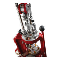
The Hornady Lock-N-Load® AP™ Primer Pocket Swage Tool is designed to remove the crimp from primer pockets, preparing spent cartridge cases for reloading. This tool is intended for use with the Lock-N-Load® AP™ press, integrating seamlessly into the reloading process to streamline case preparation.
The primary function of the swage tool is to remove the crimp from primer pockets of spent cartridge cases. Many factory-loaded ammunition cases, particularly military brass, feature a crimped primer pocket to secure the primer more firmly. This crimp must be removed before a new primer can be seated properly. The swage tool achieves this by deforming the crimp inward, creating a small radius at the edge of the primer pocket, rather than reaming or cutting material away. This method helps maintain the integrity of the primer pocket and ensures a secure fit for the new primer.
The tool operates in a multi-station setup on the Lock-N-Load® AP™ press. Cases are first inserted into an alignment die, then moved to the swage die where the crimp is removed, and finally advanced to a stripper die which facilitates case removal. The process is designed to be progressive, allowing for efficient processing of multiple cases.
The Hornady Lock-N-Load® AP™ Primer Pocket Swage Tool is designed for ease of setup and operation within the Lock-N-Load® AP™ reloading press system.
Proper maintenance is essential to ensure the longevity and optimal performance of the Hornady Lock-N-Load® AP™ Primer Pocket Swage Tool.
| Type | Progressive Reloading Press |
|---|---|
| Stations | 5 |
| Priming System | Automatic |
| Case Feeder | Optional |
| Bullet Feeder | Optional |
| Auto Indexing | Yes |
| Bushing System | Lock-N-Load Bushing System |
| Powder Measure | Included |