EasyManua.ls Logo

Hornby HM DCC HM7000 Series User Manual

Hornby HM DCC HM7000 Series
130 pages
To Next Page IconTo Next Page
Page #1 background imageLoading...
Page #1 background image
KW/CR Version 1.0 060323

Table of Contents

Question and Answer IconNeed help?

Do you have a question about the Hornby HM DCC HM7000 Series and is the answer not in the manual?

Hornby HM DCC HM7000 Series Specifications

General IconGeneral
BrandHornby
ModelHM DCC HM7000 Series
CategoryMedia Converter
LanguageEnglish

Summary

Sound Decoder First Time Use

Unboxing and Initial Setup

Covers the initial steps after unpacking a sound decoder and basic setup procedures.

Getting the Hornby HM7000 App

Instructions for downloading and installing the required Hornby HM7000 mobile application.

Setting Up and Linking the Decoder to the App

App Setup and Decoder Linking Procedure

Step-by-step guide on configuring the app and linking your new decoder.

Configuring Locomotive Address and Control Mode

Setting the locomotive's address and selecting control modes like DCC or Bluetooth.

Downloading and Installing Sound Profiles

Understanding the Reference Manual

Manual Scope and Conventions

Explains the manual's structure, scope, and naming conventions used throughout.

Hardware Naming and OTA Definition

Defines hardware terms like HFO/AUX and the OTA update process.

HM7000 Series Decoders Explained

Decoder Modes: DCC, Bluetooth, and DC Operation

Details the operational modes available for HM7000 decoders.

Bluetooth Operation Advantages

Recommendations Against DC Operation

DC Power Supply Considerations

Suitable Hornby Power Supplies

Lists recommended Hornby power supplies for HM7000 decoders.

Warning: Alternative Power Sources

Advises on the risks and considerations of using non-standard power sources.

HM7000 Decoder Core Features

HM7000 Decoder Family Introduction

Decoder Connection Types Overview

Introduces the various connection types available across the HM7000 decoder range.

Sound Decoder Types and Connection

21 Pin BLE Decoder (HM7000-21TXS)

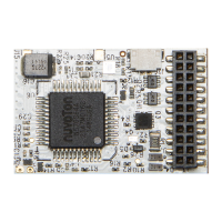
Details the specifications and pinout for the 21-pin sound decoder.

8 Pin BLE Decoder (HM7000-8TXS)

Next 18-S Pin BLE Decoder (HM7000-N18TXS)

Non-Sound Decoder Types and Limitations

Operational Limitations for Non-Sound Decoders

Outlines features not supported or requiring different procedures for non-sound decoders.

8 Pin BLE Decoder (HM7000-8)

6 Pin BLE Decoder (HM7000-6)

Decoder Function Lists and Descriptions

General Function Information

Provides a general summary of function ranges for sound and non-sound decoders.

Sound vs. Non-Sound Decoder Functions

Details the specific function ranges for sound and non-sound decoder types.

Electro-Diesel Sound Decoder Functions

Diesel Sound Decoder Functions

Electric Sound Decoder Functions

Steam Sound Decoder Functions

Non-Sound Decoder Functions

Decoder Firmware, Updates, and Support

Over-The-Air (OTA) Updates Process

Explains how to perform firmware updates wirelessly via the mobile app.

Sound Profile Management for Locomotives

Guides on installing and updating sound profiles for specific locomotives.

Sound Decoder Firmware Structure

Decoder Firmware Components Explained

Details the internal firmware structure including LDROM, APROM, and SPIROM.

Firmware Version Identification

HM7000 Bluetooth Mesh System

Common Configuration Variables (CVs)

CV1: Primary Address and CV2: Vstart

Configuration for basic locomotive address and motor start voltage.

CV3: Acceleration Rate and CV4: Deceleration Rate

Settings to control the locomotive's acceleration and deceleration behavior.

CV5: Vhigh (Maximum Speed Voltage)

Sets the motor voltage level for the maximum speed step.

CV6: Vmid (Mid-Speed Voltage)

CV7: Manufacturer Version Number

Provides information on the manufacturer's firmware version number.

CV8: Manufacturer ID and Reset Function

Contains manufacturer ID and functionality for resetting the decoder.

CV10: BEMF Cut-out Speed Step

CV12: Decoder Control Mode Selection

CV17/18: Storing Long Decoder Addresses

CV19: Consist Setup Configuration

CV27: Asymmetric DCC (ADCC) Configuration

CV29: Decoder Configuration Overview

CV29 Bit Breakdown: Motor Direction & Lighting

CV29 Bit Breakdown: Power Conversion Mode

CV29 Bit Breakdown: RailCom & Speed Table Select

CV29 Bit Breakdown: Address Selection

CV47-49: Control Processor Firmware Version

Lighting Configuration (CV51-CV58)

Hi-Level Outputs for Lighting (HFO1-HFO4)

Details on using HFOs for controlling locomotive lighting systems.

Logic-Level Outputs for Ancillary Features (HFO5-HFO6)

Explains the use of logic-level outputs for controlling other features.

Setting Lighting Effects and Brightness

Auto Function Control (AFC) Setup (CV59-CV66)

Speed Table Configuration (CV67-CV94)

Special Decoder Functions

Function Mapping and Special Features

Details special function mapping for sound and non-sound decoders.

Shunting Mode Configuration (F25/CV120)

Explains how to configure and activate shunting mode.

Creep Mode and Coupling Assist Configuration

Manual Brake Application Setup (F27/CV123)

Automatic Spot Sound Play (AFC) Configuration

AFC Sound Selection and Programming

Calculating CV Values for AFC Sound Selection

Push Button Motor Control (Non-Sound Decoders)

Sound Volume Adjustments

Global Sound Volume Control (CV158)

Sets all sound volumes to a common level using a global CV.

Specific Locomotive Volume Settings

Adjusts volumes for Steam, Diesel, and Electric locomotive sound engines.

Volume Control for Specific Functions (CV159-CV161)

Individual Spot Sound Volume Control (CV162-CV180)

Sound ID and Version Information (CV200-CV203)

Horn and Whistle Selection (CV205-CV208)

Diesel Engine Running Sound Playback

3 Notch and 4 Notch Diesel Systems

Configuration details for 3-notch and 4-notch diesel engine sound playback.

Diesel Sound System Operation Details

Diesel Operation Examples: Acceleration

Diesel Start Delay After Brake Release (CV225)

Electric Locomotive Engine Sound Playback

Electric Engine Rev Levels Explained

Details the different rev levels (notches) for electric locomotive sounds.

Electro-Diesel Locomotive Sound Playback

Diesel and Electric Components in Electro-Diesel

Explains the diesel and electric engine parts within electro-diesel locomotives.

Steam Locomotive Engine Sound Features

Non-Synchronised Wheel Chuff System

Details the simulation of steam locomotive wheel chuffing sounds.

Automatic Wheel Slip Simulation Configuration

Appendix 1: Understanding Configuration Variables (CVs)

What are CVs? Bytes and Bits Explained

Explains the fundamental concepts of Configuration Variables and binary data.

Converting Decimal Numbers to Binary

Converting Binary Numbers to Decimal

Appendix 2: Decoder Addressing Explained

Decoder Addressing Definitions and General Description

Defines short and long addresses and how they are stored in decoders.

Address Selection: Short vs. Long Addresses

How Short and Long Addresses Are Stored

Details the storage methods for short and long decoder addresses.

Controller Handling of Decoder Addresses

Appendix 3: Using AUX Outputs (HFOs)

Introduction to AUX Outputs (HFOs)

Explains the purpose and function of AUX outputs and HFOs.

HFO Electrical Information and Current Limits

Provides details on HFO types, voltage, current capabilities, and limitations.

Connecting LEDs to Decoders (8, 21, Nex18)

Connecting LEDs to 6-Pin Decoders

LED Current Draw and Resistor Calculation

Bi-Colour LED Types and Connections

LED Types and Sizes Explained

Filament Bulb Load Types

Resistors and Power Dissipation

Load Type: Relays

Relays and Flyback Diode Protection

Appendix 4: Asymmetrical DCC Control (ADCC)

ADCC Signal Explanation

Explains the concept and waveform of Asymmetrical DCC Control.

Implementing ADCC with Diode Circuits

ADCC Configuration: Rail Select (CV27)

ADCC Automatic Actions (CV125-127)

Appendix 5: Reserved Page

Appendix 6: Motor Control and Tuning

Introduction to Motor Control Tuning

Explains the importance and process of tuning locomotive motor control.

Understanding Speed Curves

Describes the relationship between speed steps and motor voltage.

The Basic Speed Curve Explained

Details the default 3-point speed curve configuration.

The Complex User-Defined Speed Curve

Explains the user-definable speed curve using multiple CV values.

What is a Motor Control Algorithm?

Tuning Motor Control Algorithms

Outlines the stages and methods for tuning motor control algorithms.

HM7000 Motor Control Tuning Stages

Stage 1: Auto-Calibration Procedure

Step-by-step guide for performing the auto-calibration process.

Stage 1 Motor Control Algorithm CVs

Stage 2: PA Control Factors Adjustment

Stage 3: PID Control Algorithm (Manual Tuning)

PID Motor Control Algorithm CVs

Lists the CVs used for manual PID tuning of motor control.

How PID Motor Control Works

Appendix 7: Power Bank and Stay Alive System

Smart Charging Functionality

Explains the smart charging feature for the Power Bank.

Appendix 8: Complete CV List for Decoders

Appendix 9: Decoder Specifications

Sound Decoder Specifications

Details operational, electrical, and physical specs for sound decoders.

Non-Sound Decoder Specifications

Details operational, electrical, and physical specs for non-sound decoders.

Appendix 10: Getting Help and Support

Appendix 11: Manual Revisions and Changes

Related product manuals