EasyManua.ls Logo

Hornet F/A-18 - User Manual

Hornet F/A-18
8 pages
Print Icon
To Next Page IconTo Next Page
Loading...
PAGE 1
F/A-18 HORNET ASSEMBLY INSTRUCTIONS
Please use extreme caution in the building of the defence paper
models. Parental permission, help and supervision is required if
being built by people under 18 years of age. Only build defence
paper models in a stable, dry, well lit area.
The suitable minimum age is 14+ years due to the accurate
cutting and folding requirements, and the need to use a sharp
hobby knife or scissors to cut the fi ne corners and details.
Do not attempt to build defence paper models if you are on
medication or under the infl uence of alcohol.
F/A-18 HORNET ASSEMBLY INSTRUCTIONS
Question and Answer IconNeed help?

Do you have a question about the Hornet F/A-18 and is the answer not in the manual?

Summary

Safety and Handling Precautions

Building Safety Guidelines

Guidelines for building defence paper models, including parental supervision and suitable environments.

Age and Substance Restrictions

Minimum age requirement and warnings against building under medication or alcohol influence.

F;A-18 Hornet Overview

Aircraft Specifications

Technical details of the F/A-18 Hornet, including crew, weight, speed, and range.

Model Component Preparation

Cut-Out Parts Diagram

Diagram showing all F/A-18 Hornet paper model components to be cut out for assembly.

Nose Section Assembly

Cutting and Folding Nose Parts

Instructions for cutting out and folding the initial parts for the aircraft's nose section.

Securing the Nose Assembly

Steps for assembling and securing the nose tip, tabs, and internal folds.

Fuselage Assembly

Forming the Fuselage Shape

Folding and shaping the main fuselage components according to dotted lines and adjacent lines.

Attaching Front and Rear Sections

Steps for folding flaps, securing tabs, and joining fuselage sections together.

Joining Major Components

Securing Fuselage Tabs and Brace

Instructions for pushing tabs into slots, securing rear tabs, and placing the brace under wings.

Connecting Nose and Fuselage

Steps for joining the nose section with the fuselage, tucking tabs, and sliding sections together.

Wing and Tail Assembly

Assembling and Attaching Wings

Steps for folding wing shapes, attaching them to the aircraft, and securing with tabs.

Assembling and Attaching Tail

Instructions for assembling the tail section and attaching it to the fuselage.

Final Assembly and Display

Assembling Rear Wing and Stand

Steps for assembling the rear wing and the display stand by folding and slotting parts.

Finished Model and Congratulations

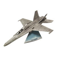
Final assembly steps leading to the finished F/A-18 Hornet model and congratulatory message.

Overview

The F/A-18 Hornet is a multi-role fighter aircraft designed for the Royal Australian Air Force (RAAF). It is capable of performing both air-to-air and air-to-ground missions, making it a versatile asset in military operations. Its capabilities include air interception, air combat, close air support for ground troops, and interdiction of enemy supply lines, including shipping.

Technical Specifications:

  • Crew: One or two
  • Weight: 10,660 kg basic, 20,412 kg (maximum)
  • Speed: Max. Mach 1.8 (2,200 km/h)
  • Range: Radius of 2,700 km (without refuelling)
  • Weapons: The F/A-18 Hornet is equipped with a comprehensive array of weaponry, including:
    • AIM-120 AMRAAM active radar guided missiles
    • AIM-132 ASRAAM missiles
    • Harpoon anti-ship missiles
    • Conventional, laser-guided, and GPS precision weapons
    • M61 20 mm nose-mounted cannon

Usage Features (Paper Model Assembly):

The provided manual details the assembly of a paper model of the F/A-18 Hornet, designed for enthusiasts aged 14 and above due to the precision required for cutting and folding. The assembly process is broken down into 41 steps, guiding the user through the creation of the aircraft and its stand.

Assembly Steps Overview:

  1. Cut Out All Shapes: The initial step involves carefully cutting out all the individual paper shapes provided in the cut-out section. Special attention is needed for slits indicated by solid internal lines.
  2. Making the Nose Section: This step focuses on assembling the nose of the aircraft.
  3. Folding Inwards: The piece is turned over, and the two sides are folded up, with the outermost crease on each side tightly folded.
  4. Curl the Nose: The nose is curled over the opposite side, creasing at each dotted line, and tucked underneath.
  5. Secure Nose in Place: The piece is turned over, and a tab is pushed into its matching slot to secure the nose.
  6. Fold Small End Flap Inwards: The piece is turned back over, and the small end flap is folded inwards to further secure the nose.
  7. Creating the Nose Tip: The nose tip is folded inwards at each dotted line.
  8. Push Tabs into Matching Slots: The two sides are tucked in, and the long flap is folded over, pushing the tabs into their matching slots.
  9. Fold the Dotted Lines Inwards: The dotted lines at the rear of the piece are folded inward.
  10. Assembling the Fuselage: This step initiates the assembly of the main body of the aircraft.
  11. Folding the Fuselage: The fuselage is folded inward down the centre dotted line and outward along the two adjacent lines.
  12. Fold Front Flaps: The front-side flaps are folded underneath the fuselage.
  13. Turn Over and Fold Outwards: The piece is turned over, and folds are made outwards at the next adjacent line on each side.
  14. Fold Outwards Again: Folds are made outwards again at the next adjacent line on each side.
  15. Turn Over and Fold Inwards: The piece is turned over, and the tabs on the inner-front are folded inwards.
  16. Slot the Tabs Together: The tabs are carefully slotted together.
  17. Fold Wingtips Inwards: The wingtips are folded inwards on both dotted lines at the end of each wing.
  18. Turn Over and Fold Inwards: The piece is turned over, and the rear section is folded inwards.
  19. Push Tabs into Slots: Folds are made inwards at each dotted line, and tabs are pushed into their matching slots to secure.
  20. Fold Inward at Dotted Lines: The end section is folded inward at the dotted lines.
  21. Secure Tabs into Slots: The end section is brought over, and tabs are pushed into matching slots to secure.
  22. Joining the Nose and Fuselage: The nose section and fuselage section are brought together.
  23. Slide Fuselage into Nose: The fuselage section is slid into the nose section, ensuring the rails hook together.
  24. Tuck Fuselage Tabs into Nose: The fuselage is slid all the way forward, and the tabs at the front of the fuselage are tucked under the nose.
  25. Push Tabs Through Slots: The aircraft is turned over, and tabs are pushed through their matching slots to secure.
  26. Slide Brace Under Wings: The bracing piece (A) is slid between the two objects until it sits evenly across both wings.
  27. Push Rear Tabs into Slots: The rear tabs are pushed into their matching slots.
  28. Assembling the Wings: This step begins the assembly of the wings.
  29. Fold Inward at Dotted Lines: Each wing is folded inward at each dotted line to create its shape.
  30. Attach Wing to Aircraft: The wing is placed over the aircraft, with the tabbed side on the underside.
  31. Tuck Tab into Slot: The tab is tucked into its matching slot to secure the wing. Steps 28 to 31 are repeated for the other wing.
  32. Assembling the Tail: This step focuses on assembling the tail section.
  33. Fold Tail in Half and Attach: The tail is folded in half and pushed into the slot on top of the fuselage, then pulled backwards to secure. This process is repeated for the other tail.
  34. Assembling the Rear Wing: This step begins the assembly of the rear wing.
  35. Attach to Rear of Plane: The rear wing is folded in half, pushed into the slot at the rear of the aircraft, and pulled backwards to secure.
  36. Repeat: Steps 34 and 35 are repeated for the other side.
  37. Assembling the Stand: This step initiates the assembly of the display stand.
  38. Fold Inward at Dotted Line: The stand piece is folded inwards at each dotted line.
  39. Slot Together Matching Tabs: The matching tabs inside the stand are carefully slotted together.
  40. Cut Out All Shapes (Stand): All remaining shapes for the stand are cut out, ensuring slits where solid internal lines are shown.
  41. The Finished Model: Congratulations on completing the F/A-18 Hornet model.

Maintenance Features (Safety Guidelines for Paper Model Assembly):

The manual emphasizes safety precautions for building the paper models:

  • Caution: Extreme caution is advised during construction.
  • Parental Supervision: Parental permission, help, and supervision are required for individuals under 18 years of age.
  • Work Environment: Models should only be built in a stable, dry, and well-lit area.
  • Minimum Age: The suitable minimum age is 14+ years due to the accurate cutting and folding requirements, and the necessity of using sharp tools like hobby knives or scissors for fine details.
  • Impairment: Do not attempt to build defence paper models if under the influence of medication or alcohol.

Hornet F/A-18 Specifications

General IconGeneral
BrandHornet
ModelF/A-18
CategoryToy
LanguageEnglish