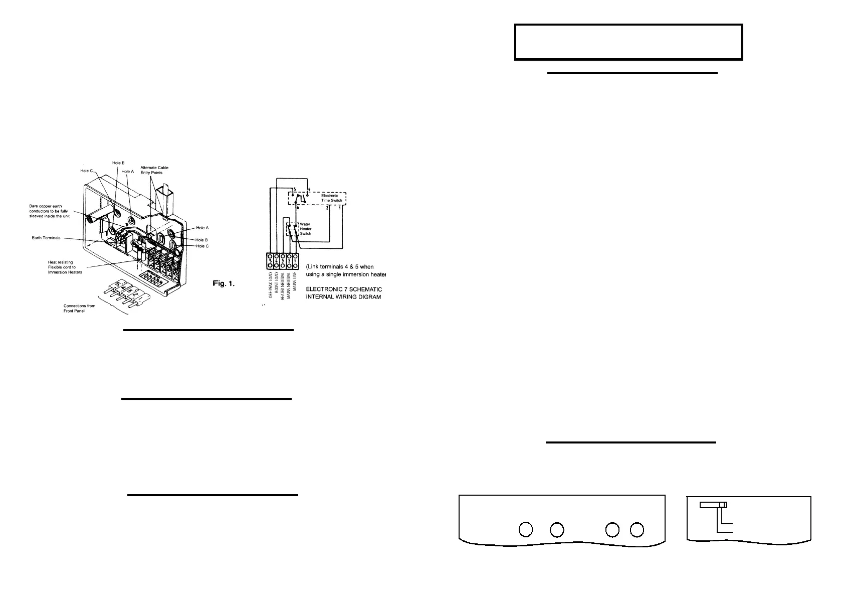
CONNECTIONS
Use a three-core cable with a minimum conductor size of 1.0mm
2
for a 2kW heater, or 1.5mm
2
for a
3kW heater to connect the unit to the supply. Connect the incoming wires to the terminal block as
follows;
TERMINAL 1 - LIVE in
TERMINAL 2 - NEUTRAL in
TERMINAL 3 - NEUTRAL(s) outtoimmersionheater(s)
TERMINAL 4 - LIVE out to Boost immersion heater
TERMINAL 5 - LIVE out to Off-Peak immersion heater
Clamp all surface wiring adjacent to the box or use trunking where appropriate. Secure the heat
resistant flexible cords from the immersion heaters using the cable clamp in the box.
SINGLE ELEMENT IMMERSION HEATERS
The 3 core flexible cord should be heat-resistant and rated to 85
o
C.
TERMINAL 4 (Boost live output) should be connected to TERMINAL 5(Off-Peak live output) and to the
immersion heater.
The Neutral connection should go to TERMINAL3 and the Earth connection to the EARTH TERMINALS.
DUAL ELEMENT IMMERSION HEATERS
The elements should be controlled through separate thermostats. In practice the thermostat for the
top short element is usually set
5-10
o
Cless than the thermostat for the long Off-Peak element.
The 3 core flexible cords should be heat-resistant and rated
85
o
C.
TERMINAL 4 (boost live output) should be connected to the short element and TERMINAL 5(Off-Peak
live output) to the long element.
The Neutral connections should go to TERMINAL 3and the Earth connection to the EARTH TERMINALS.
TWIN IMMERSION HEATERS
The thermostat for the top immersion element should be set lower than the thermostat for the
bottom immersion heater.
The 3 core flexible cords should be heat-resistant and rated
85
o
C.TERMINAL 4(boost live output)
should be connected to the top immersion heater and TERMINAL 5(off-peak live output)to the bottom
immersion heater. The two Neutral connections should go to TERMINAL 3and the Earth connections to
the EARTH TERMINALS
COMMISSIONING INSTRUCTIONS
SETTING THE CONTROLLER
A feature of this controller is that it allows the time of day and Off-Peak switching times to be set
before the unit is finally installed and powered up.
COMMISSIONING SWITCH
The commissioning switch which is on the back of the unit must now be set to achieve correct
operation of the controller and battery reserve. The display will remain blank with the switch in the
OFF position.
RESETTING THE ELECTRONIC 7
Before installing the off-peak heating periods it is important to reset the unit, this is achieved by
simultaneously pressing the Boost, Summer/Winter, HrsandMins buttons together. The Boost
selection switch must be in the Manual Boost Position.
Electronic equipment can sometimes be affected by sudden changes of atmosphere, this can result in
Display being fogged or Reset function failure. If this happens leave the unit switched on for 15
minutes and repeat the RESET function.
BOOST
SUMMER/
WINTER
HRS MINS
MANUAL BOOST
TIMED BOOST
BOOST SELECTION
SWITCHPOSITION - GMT or GMT/BST
It is essential that the correct commissioning switch position is selected. Incorrect setting of the
commissioning switch may result in inefficient use of the available Off-Peak supply.
GMT ONLY- Switching will always take place at GMTtimes (summer and winter).
GMT/BST- Switching time will be changed by one hour, when the user presses
SUMMER/WINTERbutton on the face of the unit. In the GMT/BSTmode the clock display will match
the actual switching time.
If connection is to be made where a 2-Rate electricity meter is controlled by a Radio Teleswitch or
other equipment, which control tariffs remotely or seasonally, it is essential that before setting the
commissioning switch you find out how the off-peak times are controlled.
The Customer Service Centre of your Electricity Supplier will confirm information regarding Off-Peak
electricity timing and the switching method used for your area. (see below)
GMT ONLY- Set the switch in the GMT position, switching will always take place at GMT
times (summer and winter).
GMT/BST- Set the commissioning switch in the GMT/BST position. Switching time will be
changed by one hour, when the user presses SUMMER/WINTERbutton on the face of the unit. In the
GMT/BSTmode the clock display will match the actual switching time.
On installations where the 2-Rate electricity meter is controlled by a mechanical Tariff Timeswitch the
commissioning switch should be set to GMT ONLY.
PAGE 2 PAGE 3
When wiring is complete ensure that all terminal screws,
including the earth terminal screws are securely tightened
to achieve a minimum torque of .75Nm.
 Loading...