Hospitex Diagnostics EOS Bravo and EOS Bravo Plus Service Manual
29
3 - ASSEMBLY AND ADJUSTEMENT
1) position the instrument with the door with the boards towards you.
2) assembly the CPU board fixing it with the four screws on the angles, do not insert any
connectors.
3) assembly the Power board fixing it with the four screws on the angles, plus the central screw
which is positioned between the connectors J1 and J2. Do not insert any connector or fuses.
4) Fix the fuses 5x20 mm of 3,15 A (6,3 for the alimentation at 110 Volt) into the fuses holder of
the net entrance module.
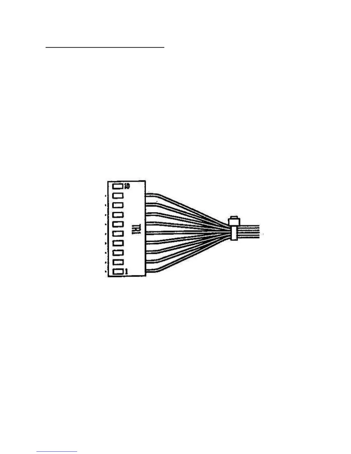
5) Connect the alimentation, turn on the instrument and measure the exit tension of the
transformer on the TR1 connector (MX396 10 poles) of the cablings according to the
following scheme:
- pin 1 <> 2 = 20 Vac (acc. of 20 to 22 V)
- pin 3 <> 4 = 8 Vac (acc. of 8 to 9 V)
- pin 4 <> 5 = 8 Vac (acc. of 8 to 9 V)
- pin 3 <> 5 = 16 Vac (acc. of 16 to 18 V)
- pin 6 <> 7 = 11 Vac (acc. of 11 to 12 V)
- pin 8 <> 9 = 5,5 Vac (acc. of 5,5 to 6,5 V)