Hospitex Diagnostics EOS Bravo and EOS Bravo Plus Service Manual
30
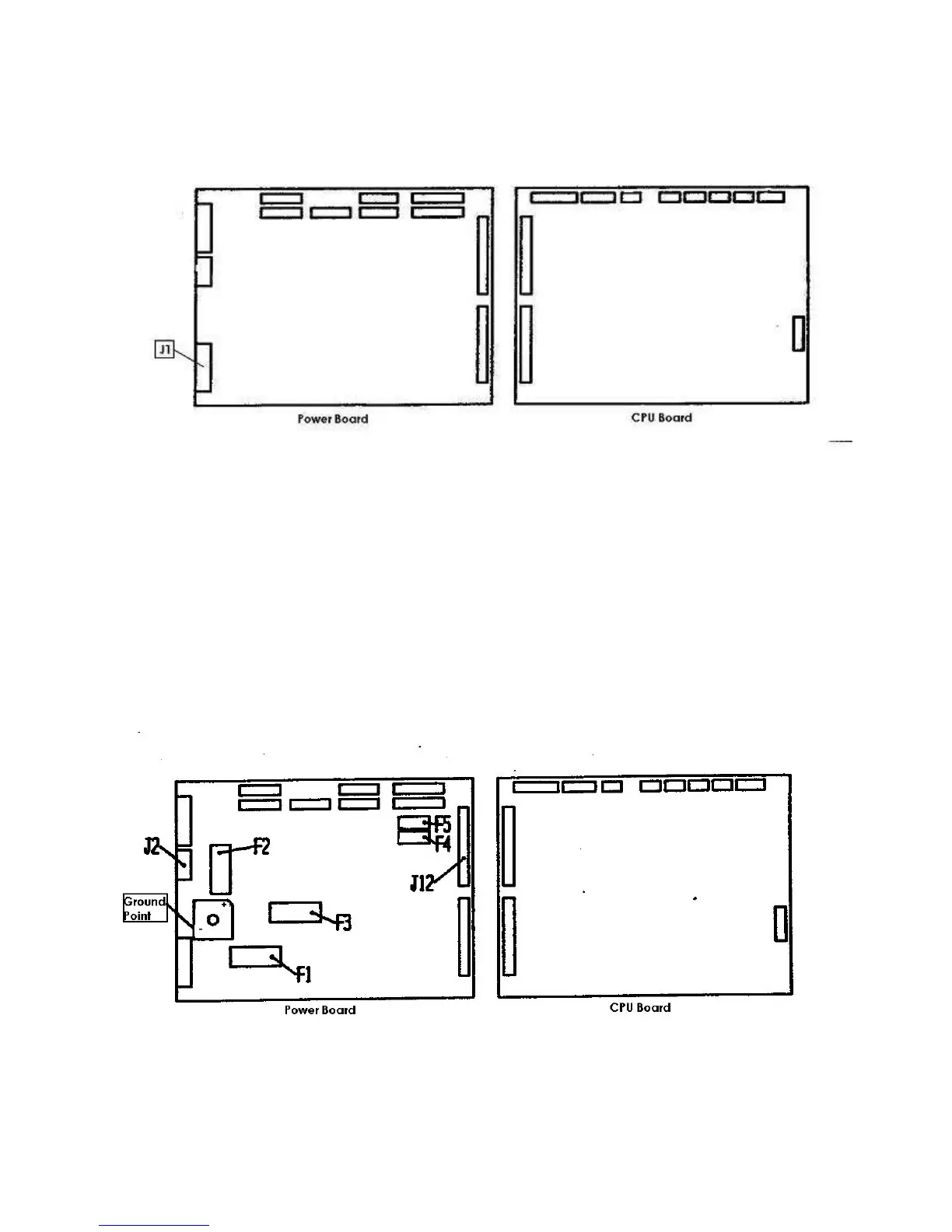
6) turn off the instrument and connect the connector of the cabling with the note TR1 (MX396
10 poles) on the connector J1 of the Power board.
WARNING: form this moment avoid to position your face on the boards (in particular the
power board) when the instrument is turned on.
7)
turn on the instrument and measure the stabilizing tensions connecting the negative end of
the tester of the ground and the positive end on the exit point of the fuses holder on the power
board following the below scheme:
- F1 = +28 Vcc ( acc. of 28 to 30 Vcc )
- F2 = + 7 Vcc ( acc. of 7 to 8 Vcc )
- F3 = +15 Vcc ( acc. of 15 to 16 Vcc )
- F4 = +11 Vcc ( acc. of 11 to 12 Vcc )
- F5 = -11 Vcc ( acc. of 11 to 12 Vcc )